DIY do it yourself
Master classes, instructions, useful tips, recipes.
» » »Stable beetle at 100 meters
Below is the design of a radio transmitting device with a range of up to 100 meters.
Such a radio bug was built according to the three-point capacitive scheme (like all other known schemes), the components were carefully selected. The frequency does not swim, as is the case with many radio bug schemes. If you stand with the receiver at a distance of 1, 10 and 50 meters from the beetle, then the frequency drift will be only 100-120 kHz - which you will agree is very small, and can not affect the quality of wiretapping.

Stable beetle at 100 meters


The beetle can be used for directional wiretapping of rooms and even objects that are in motion! This was made possible thanks to the selection of transmitter components, which makes the modulated signal quite stable, and the circuit at the same time remains simple and affordable even for a beginner radio amateur.
In the transmitter, the use of high-frequency and microwave transistors of low power is possible. It is advisable to use transistors with a cutoff frequency of 700-1000 MHz. The domestic KT368 (which is a complete analogue of the transistor indicated in the circuit) is perfect.
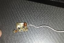
To increase the sensitivity of the radio microphone, an additional microphone amplifier was used, the circuit of which is built on only one transistor.
The transistor is literally any low-power - KT3102, KT315, KT368, C9014, C9018 and others similar. Such an amplifier makes it possible to catch even a quiet whisper in a 4x4 meter room. The sensitivity of the bug is about 5 meters.
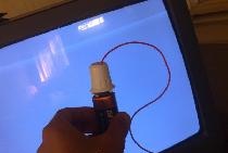
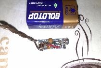
Antenna - stranded wire in rubber insulation with a length of 10-25cm.

Stable beetle at 100 meters


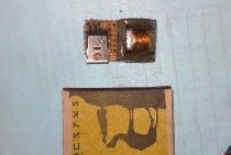
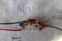
The coil consists of 5 turns, wound on a frame with a diameter of 3-4mm. As a frame, you can use a paste from a helium pen. For the circuit, you can use a wire with a diameter of 0.5-1.2 mm (in my case, 0.8 mm).
The microphone can be taken from almost any electronic soundtrack, sensitivity is not very important, because the bug has an additional microphone amplifier.
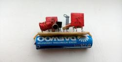
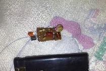
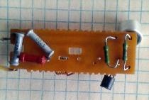
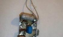
All installation was done on a breadboard, because I did not want to poison the board for the beetle, the performance of which is not yet clear. Resistors are sealed on the back of the board.

Stable beetle at 100 meters


To tune to the desired frequency, a variable capacitor was used, which, after full tuning, was replaced by a constant capacitor (capacity 18 picofarads). By rotating this capacitor, you can tune the bug to the frequency you need.
The beetle operates at frequencies of 96-99 MHz, caught on a regular FM receiver. With a high-quality receiver, the bug can be caught at a distance of up to 150 meters.

Stable beetle at 100 meters

Stable beetle at 100 meters

Stable beetle at 100 meters

Stable beetle at 100 meters
come back
Comments (23)
  1. Dmitry Vladimirovich
    #1 Dmitry Vladimirovich Guests January 25, 2013 21:51
    0
    The frequency stability of such circuits is determined mainly by the mutual orientation of the field of the contour coil and other active parts of the circuit. But not only that.Reliability and communication range as a whole still strongly depends on the parameters and properties of the receiver. For example, a too narrow passband of the IF path, although they increase sensitivity, but like a too "slow" loop of the AFC lead to a sharp breakdown in reception of an unstable transmitter. For information, in the best Soviet household FM receivers, the bandwidth was within 200 ... 250 kHz with a sensitivity of less than 1 μV, and the response time of the AFC was less than 0.1 sec. In military connected receivers, everything is much better. Now this can be provided only by relatively expensive devices, which does not impose super requirements on transmitters. Nowadays, there are already supercompact surfactant microcircuits with exceptional parameters. But training, of course, is cheaper on bugs.
  2. ZippyRusika
    #2 ZippyRusika Guests February 3, 2013 2:07 p.m.
    1
    Thanks for the material provided.
  3. _MiX_
    #3 _MiX_ Guests March 23, 2013 17:16
    0
    Thank you, I did it works fine, I heard a quiet whisper 5 meters from the bug
  4. Name
    #4 Name Guests April 11, 2013 13:37
    1
    And why is it "stable" ???
  5. lol228
    #5 lol228 Guests June 25, 2013 23:49
    1
    tell me where you can get all the components for this bug except the electronics store charging there and so on
  6. Alexander
    #6 Alexander Guests October 26, 2013 09:42
    0
    Tell me what I did wrong? I soldered everything according to the scheme, the current passing through the tuning capacitor was replaced by 18pF, but I still can not find the desired wave :(
  7. Oleg
    #7 Oleg Guests December 7, 2013 9:25 p.m.
    0
    Is this bug possible to build under the AM range?
  8. Ivan
    #8 Ivan Guests March 3, 2014 18:57
    0
    Tomorrow I will go for the components, I hope it will work. if that unsubscribe
  9. Ivan
    #9 Ivan Guests March 7, 2014 02:54
    0
    I went. bought it. at 18pf there were no capacitors. soldered from 2 to 10pf. does not work. it may work, but it is not known at what frequency ...
  10. Alexander
    #10 Alexander Guests June 30, 2014 10:06 p.m.
    0
    How to check the performance of the beetle? I collected, but I can not catch
  11. Vova
    #11 Vova Guests July 21, 2014 17:38
    0
    no resistor R4 on the circuit
  12. Max
    #12 Max Guests August 3, 2014 20:06
    0
    To test the performance of the circuit, an RF detector is needed.
  13. Evgeniy
    #13 Evgeniy Guests October 17, 2014 15:37
    1
    I understand this circuit is already receiving a signal?
  14. Evgeniy
    #14 Evgeniy Guests October 17, 2014 15:55
    0
    and what is the resistance of the resistor R7 ??
  15. Zil
    #15 Zil Guests December 16, 2014 10:59
    0
    Did once. Works. And with a microphone, and with a 3.5 mm output from the phone. Much depends on the length of the antenna.
  16. RW9UNK
    #16 RW9UNK Guests January 28, 2015 17:58
    1
    So then everything is clear. And what voltage to feed him?
  17. mmaid
    #17 mmaid Guests February 9, 2015 19:53
    2
    who succeeded, discard the wiring diagram please
  18. Alexander
    #18 Alexander Guests April 14, 2015 23:00
    2
    The bug feeds from 3 to 9 volts
  19. alexandor
    #19 alexandor Guests July 17, 2015 12:40
    0
    how easy it is to do at home
  20. Igor
    #20 Igor Guests November 26, 2015 00:33
    1
    Is it possible to use a wire with a diameter of 0.3 mm?
  21. Vladimir
    #21 Vladimir Guests March 18, 2016 14:57
    4
    I assembled everything according to the scheme, the only one that did not find the necessary capacitor C4, was replaced by 15pF. Sensitivity is good, range is in parts of the receiver in all parts of the apartment. But the beetle transmission frequency constantly runs away, runs away for about two minutes, tuned to 95.8 MHz, the frequency runs down after about one and a half minutes, you have to tune to 95.7, etc. Beetle powered by 3v battery. Before that, he collected a bug on one transistor, powered by a 1.5v battery, but it was rather weak and worked stably, but as soon as the voltage was increased to 3v, the frequency started to run away. Then I did not try to lower the power. What could be the problem of an unstable frequency?
  22. zor
    #22 zor Visitors March 29, 2018 14:22
    2
    The people, if not secret, but what are you listening to?))
  23. Man
    #23 Man Guests February 24, 2019 01:48
    3
    This is the simplest circuit of a radio microphone, I’ve collected it all my life for fun, instead of a microphone and the first transistor, you can put a carbon microphone, then the circuit will generally consist of one transistor. All capacitors can be made independently, a spiral of varnished wire is wound onto a thin pin of wire (the pin is the first contact, the end of the spiral is the second), 1 centimeter of the spiral is approximately 10-20 pF, then you can pick everything up by poking, just cutting off the excess capacity with scissors . With homemade capacitors, the circuit generally becomes tiny.And so that the transmission frequency does not float away from approaching a person’s antenna, you can connect the antenna to a second parallel coil, just the first coil is wound with a double wire, it turns out to be a kind of transformer, the secondary winding of which is one end - the antenna, the other end to minus. And I always tuned the frequencies not with the capacitance, but with the inductance, you just need to wind a coil for 2-3 turns, to extinguish the excess inductance with a trimming nail. The nail does not conduct a high frequency of the field, therefore, when it is thrust into the coil, the inductance drops, the turns seem to be reduced.

Read also

Error codes for washing machines