DIY do it yourself
Master classes, instructions, useful tips, recipes.
» » »Silencer for the frequency of television and radio signals
I present to your court the design of a frequency silencer. A fairly simple and 100% working circuit is designed to suppress television and radio signals. The device will be able to jam almost any TV channel (except the satellite of course) at a distance of up to 15 meters from the TV. The device itself is an interference provider, the transmitter of which is made on only one transistor.

Silencer for the frequency of television and radio signals


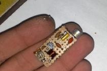
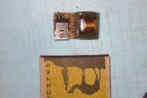
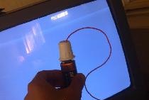
You can use literally any RF or microwave transistors. KT 368 (from the HF series) or KT 325, KT 399 (from the Microwave series) are perfectly suited. When using microwave transistors, the range increases to 50 meters. The circuit contains 5 - 6 turns of wire with a diameter of 0.5 - 0.7 mm, wound on a frame with a diameter of 4 mm. The circuit itself is quite simple and was taken from a radio bug scheme. The transmitting circuit has been replaced, the circuit has been changed so that it generates interference on the amp - band, because it is on these bands that many television and radio channels work. A piece of copper wire with a length of 20 - 15 cm serves as the antenna, the latter can be excluded, but then the distance decreases. By rotating the variable capacitor, the device can be configured to directionally suppress channels that are in close ranges. The power of the device is enough for the targeted suppression of 2 - 3 television or radio channels.

Silencer for the frequency of television and radio signals

Silencer for the frequency of television and radio signals


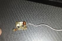
The jammer can be powered from 4 to 12 volts. For this purpose, the crown or corundum or any constant voltage sources for which the specified output rating is perfect. A precise device can also be implemented using microwave field effect transistors. The values ​​of the used radio components can be rejected in one direction or another, we are talking about resistors, because the capacitors in the circuit are critical and even with a deviation of 1 picofarad, the circuit may not work at all or work with "ailments" - short range, high current consumption, unstable work, etc.

Silencer for the frequency of television and radio signals

Silencer for the frequency of television and radio signals


The current consumption of the jammer should be somewhere around 5 - 7 mA from the crown. In order to reduce power, you can increase the emitter resistor value of 100 ohms. Thanks to this, you can achieve power in a couple of watts. Using powerful field effect transistors, you can suppress (jam) the GPS range, and therefore mobile communications, we will talk about a similar design next time.

Silencer for the frequency of television and radio signals
come back
Comments (22)
  1. igor27
    #1 igor27 Guests May 26, 2012 14:23
    1
    but can I put kt368 instead of kt325?
  2. jekawar04
    #2 jekawar04 Guests June 26, 2012 18:27
    0
    good idea! I'll try to collect!
  3. Mortem
    #3 Mortem Guests July 3, 2012 9:07 p.m.
    0
    It doesn’t work for me, like I did everything right, I etched the board myself, I feed from the crown, and nothing
  4. Vernyak
    #4 Vernyak Guests February 19, 2013 00:34
    1
    You have all the picofarad capacitors in the circuit, and in the photo there is a 10 nanofarad capacitor. A print in secheme. Did I understand correctly?
  5. Vernyak
    #5 Vernyak Guests February 19, 2013 00:36
    2
    and in the photo of the finished jammer 4 capacitors a in scheme 5
  6. Alexander
    #6 Alexander Guests May 26, 2013 23:53
    0
    Who did it work and really work?
  7. Alexander
    #7 Alexander Guests May 27, 2013 00:26
    1
    gave the circuit to the radio electronics engineer. collected and the range of not more than one meter and then drown out a specific frequency is very difficult (
  8. khanurik
    #8 khanurik Guests September 10, 2014 15:00
    2
    wink assembled a circuit. everything is working. the signal radius is 8-10 meters. it’s just that you all have hands from the wrong place.
  9. Lover
    #9 Lover Guests December 25, 2014 15:59
    0
    And kt315 does not fit?
  10. Daria
    #10 Daria Guests February 3, 2015 07:29
    0
    Make me such an order, please, who has golden hands. Need a frequency suppressor with a radius of 10-25 m (wifi, etc.)
  11. kolyan
    #11 kolyan Guests January 21, 2016 20:31
    1
    forum live? Hello !!!!
  12. George
    #12 George Guests December 26, 2016 16:10
    0
    And can she drown out the cellular signal?
    1. Alexander Glushkov
      #13 Alexander Glushkov Guests August 24, 2018 15:04
      0
      No. There are Gigahertz. 4G actually 3-4 GHz.
      1. Igor Protsenko
        #14 Igor Protsenko Visitors 17 april 2019 02:04
        0
        generally 2.4 GHz
  13. holy
    #15 holy Guests January 4, 2017 19:29
    0
    [b] Hanurik [/ b],
    And which transistor set?
  14. t212
    #16 t212 Guests November 20, 2017 00:26
    1
    Conder 10nF in the photo, most likely C5, for nutrition.
    In the photo there are 5 Conders, and in scheme 5 - KPE (with a slot for a screwdriver) is also a Conder.
    When assembling this scheme, for the best plan, you need to use C0G Conders, and thin-film SMD cuts.
    1. Guest sergey
      #17 Guest sergey Guests August 18, 2019 13:17
      0
      Incidentally, I saw only 4. including the trimmer ...
  15. t212
    #18 t212 Guests December 4, 2017 11:19 p.m.
    3
    In general, I collected this unit. As expected, the scheme is not working. Namely: the capacitor C1 value is crookedly indicated - it should be 10nF, the circuit works with such a rating.
    Everything was assembled on a 9X16mm board. 2n2222 transistor and varicap in standard cases, the rest are 0603 and 0805. All parts were taken in Mouser.
    The test result is as follows: The circuit complies with the specification, long-range, easy to repeat (if you use Conders with a minimum deviation from the recommended value).
    The disadvantage of the scheme: a very narrow suppression band - requires careful tuning to the station frequency which we press.
    Important - tuning a varicap is best done with a dielectric screwdriver.
    1. Boris
      #19 Boris Guests July 31, 2018 18:44
      2
      Varicap is such a diode and it is not twisted with a screwdriver !!! Although there may be such individuals.
    2. Igor Protsenko
      #20 Igor Protsenko Visitors 17 april 2019 02:00
      0
      you didn’t mistake the master, a varicap is a capacitive diode where did you see it here? And what circuit is it in what frequency? With such inductance it will snore dullly in the mid-wave range. The coil needs 3 turns and stretch them millimeters by 7 then at 20pf trimmer (5 -30pf) you get in somewhere at 100MHz. In general, the circuit from Matvey, dead as a dung. It's a pity the boys.
  16. Alexander Glushkov
    #21 Alexander Glushkov Guests August 24, 2018 15:01
    1
    About 40 years ago, such things were done on one tunnel diode, resistor and LC circuit, a square battery.
    Remembering the receivers of the war era, trimmer condors did this: a piece of 3 cm thick, 1 mm enameled wire on a circuit board, on which a thin, 0.1-0.25 mm enameled wire was wound round to round, which serves as another lining of the conder. Capacity is determined by the length of the winding. And by the way! C1 and C5 should be at least 0.1 microfarads. Still, a circuit with a common base, not a toy! And I still did not understand: why such a working current: almost 15 mA? It is possible and less! Then R1- 30 com.
  17. Guest sergey
    #22 Guest sergey Guests August 18, 2019 1:09 p.m.
    0
    one of the photos shows a ginger conder with a face value of 103, which corresponds to 10 * 10 ^ 3 = 10nf. something according to the scheme, I do not observe this ....

Read also

Error codes for washing machines