DIY do it yourself
Master classes, instructions, useful tips, recipes.
» » »Compact adjustable 24V 5A power supply
Compact adjustable 24V 5A power supply

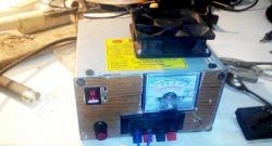
I decided to redo my laboratory power supply. Although it is reliable, it is heavy and takes up a lot of space. The desktop is always lacking. When planning a reshuffle. I decided to hang a hinged shelf and under it is full of space. The idea came quickly, I make a mounted laboratory power supply.

Will need


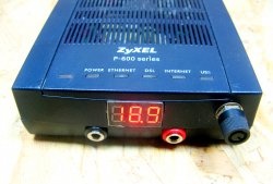
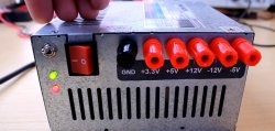
The case I will have a box from the old modem. It is full of space, and I will collect it on modules.
Compact adjustable 24V 5A power supply

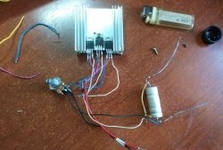
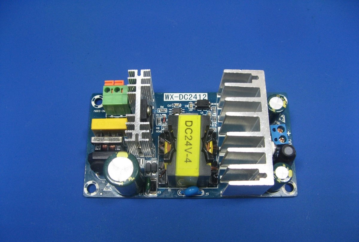
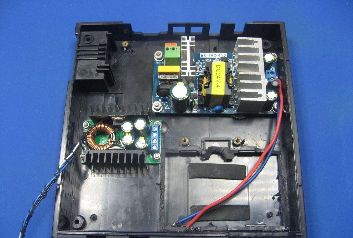
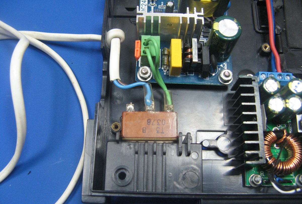
The power unit is a module from China. The output of the module is 24 volts and they promise an impressive current, as for the dimensions of the module.
Compact adjustable 24V 5A power supply

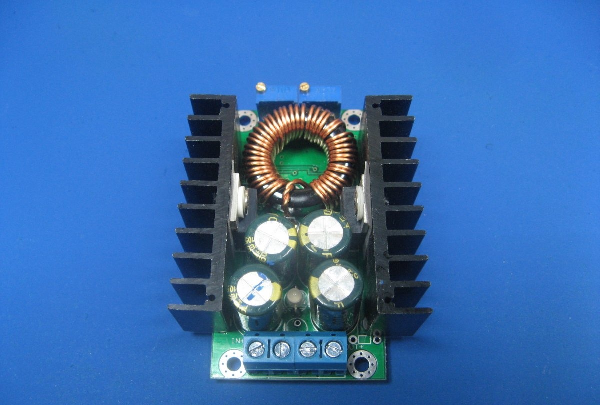
I will regulate the output voltage with the help of a ready-made module. The module is quite common, there is a lot of information about it, the price is very good.
Compact adjustable 24V 5A power supply

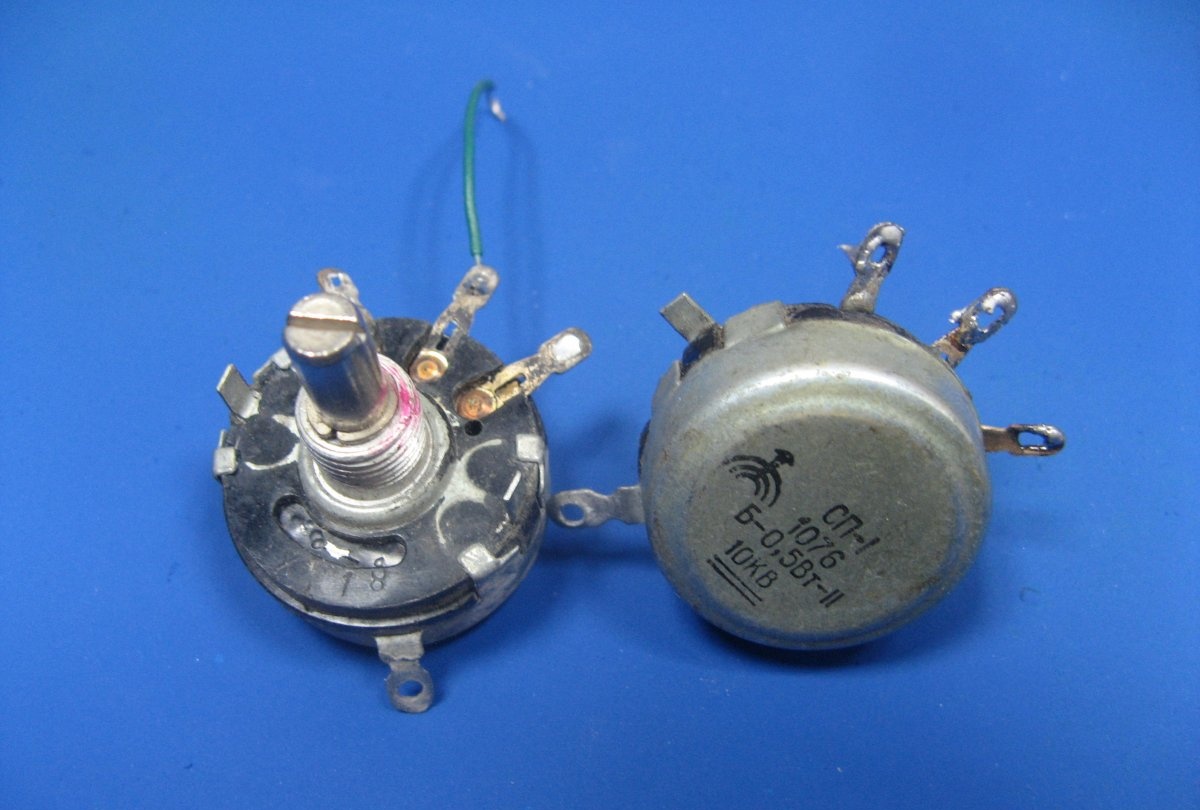
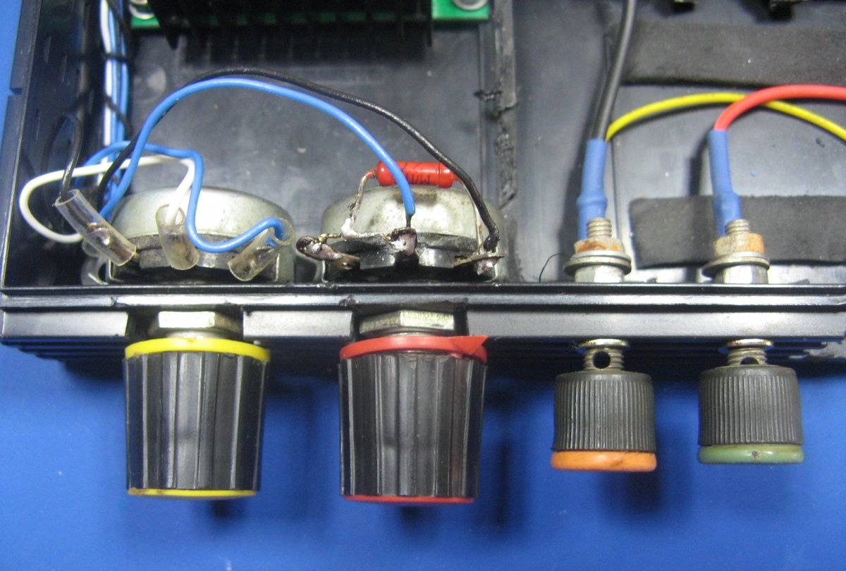
Instead of tuning resistors, I will install adjusting, domestic. It’s better to take wire resistors, of course, but I’ll apply what I have. You also need to pick up pens on them.
Compact adjustable 24V 5A power supply

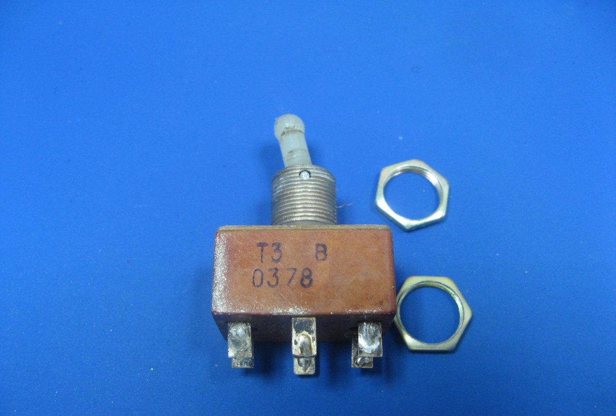
I have a network toggle switch T3, I have them with a shaft.
Compact adjustable 24V 5A power supply

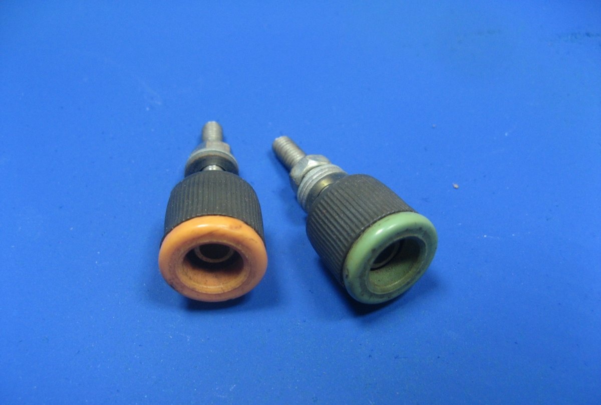
The terminals are needed in different colors, so as not to confuse when connecting devices.
Compact adjustable 24V 5A power supply

Multimeter from China. Very well established. Dimensions just right.
Compact adjustable 24V 5A power supply

Production of a laboratory unit from Chinese modules


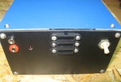
On the body, I make markings for the elements of the front panel. Cut out. The plastic is quite soft, can be cut with a sharp knife.
Compact adjustable 24V 5A power supply

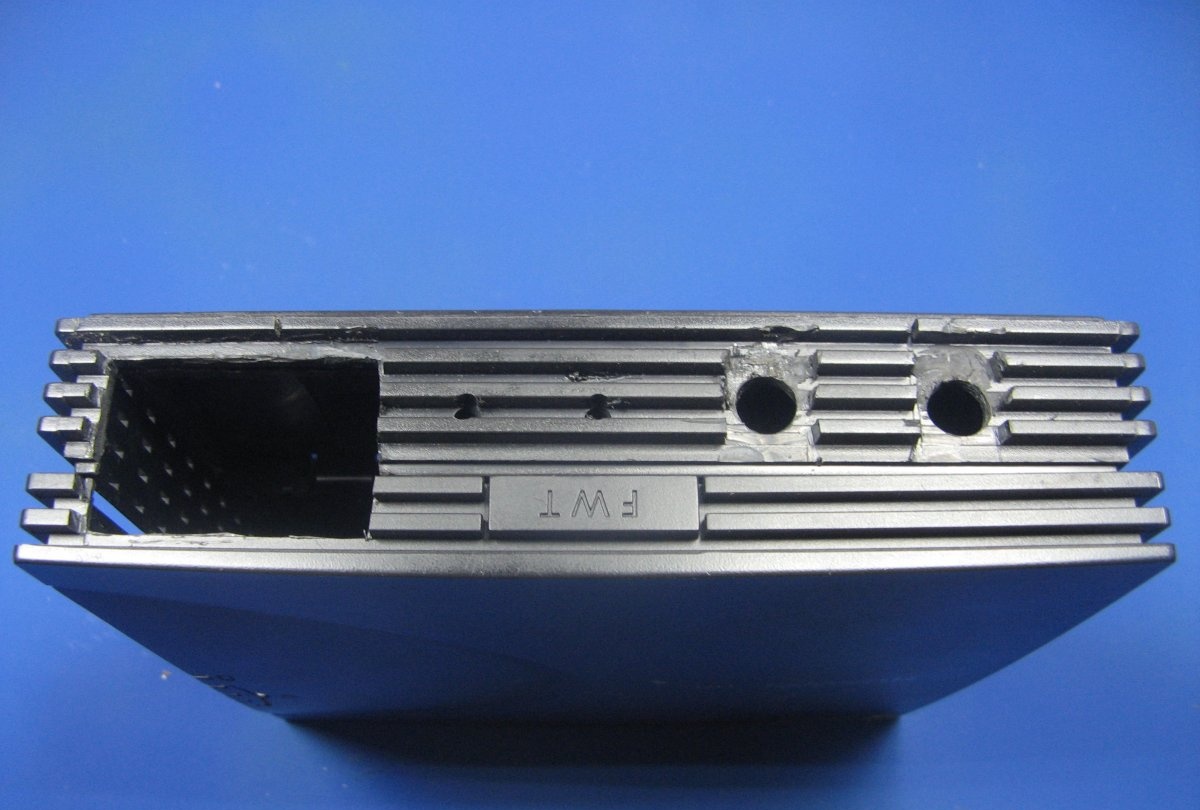
Trying on a place for the modules. I drill holes and install the modules. I install the network module on the bushings. Bushings cut from a silicone tube. I immediately screwed the output wires from the network module. He carried out the wires for the adjustment resistors. It makes no sense to draw a diagram; everything is corny simple. From the network module, the wires go to the adjustment module. The wires go to the terminals through a multimeter.
Compact adjustable 24V 5A power supply


Soldered wires to resistors. Found pens of different colors. There are 3 wires to the current control resistor, to voltage 2.
Compact adjustable 24V 5A power supply

The network wire soldered to the toggle switch. From the toggle switch, the wires go to the module. A very convenient place was under the toggle switch.
Compact adjustable 24V 5A power supply

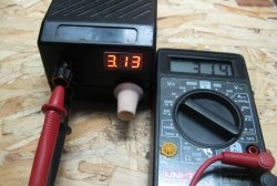
I used a stabilizer to power the multimeter. Assembled stabilizer on TL431. You can not put it, but decided to play it safe. It can be powered from 24 volts. The stabilizer can be calculated on the Internet.
Compact adjustable 24V 5A power supply

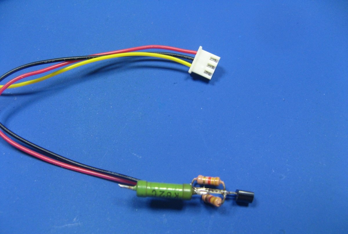
For smooth adjustment, a constant resistor of 27 kOhm was installed in parallel with the adjustment resistor.
Compact adjustable 24V 5A power supply

Connected input and output wires to the control module. The stabilizer for the multimeter was also screwed to the module. The stabilizer filled thermo with glue.
Compact adjustable 24V 5A power supply

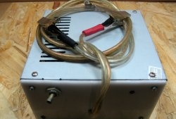
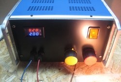
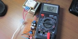
I close it. I turn it on. I connected the car lamp to the output. Stabilization works fine.
Compact adjustable 24V 5A power supply

Laboratory power supply fits perfectly in the workshop. Does not take up space. Convenient to use

Links to modules:


Watch the video


come back
Comments (6)
  1. Guest Yuri
    #1 Guest Yuri Guests July 29, 2019 8:50 PM
    2
    Is this a 4A impressive current? At maximum load, these blocks will become very hot. I did something similar. Ripples for the lab technician are simply unacceptable. Yes, and stabilization is in question. At the end of the video on YouTube, the voltage and current drop in your system, but you cheerfully report that everything works. Dislike definitely!
  2. Guest Vitaliy
    #2 Guest Vitaliy Guests July 30, 2019 06:29 AM
    2
    So here with your own hands only the casing is washed down the rest is ready!
  3. Guest Alexander
    #3 Guest Alexander Guests July 30, 2019 3:15 p.m.
    0
    It's ridiculous! DIY what? indicate at least what blocks were used and how they work. The problem is clear. Well, it happens.
  4. Guest Victor
    #4 Guest Victor Guests July 31, 2019 09:11
    2
    Norm idea. Everyone can only blame. I met the like, just lying on the table. Not the case for you, not the design. All correctly assemble and install in the housing, you also need to know how. During development, I pulled a bunch of semiconductors. Ripples can be defeated, in an Internet full of ways.
  5. Guest Alexander
    #5 Guest Alexander Guests August 5, 2019 9:25 p.m.
    0
    no one says that the idea is bad, you just need to be simpler without loud headlines and do it yourself and explain what you did
  6. Guest Oleg
    #6 Guest Oleg Guests August 6, 2019 11:59
    1
    This PSU from ready-made Chinese units in the network is already a million only in cases differ. No amateur performances, fantasies. I assembled my 23 V and 6 A PSUs from a pulsed PSU from a printer and cut out a little alteration from the general board, and I got an excellent 23 V PSU. Adjustment on the same unit from China just put a 12 V fan on and powered it and the indicator (voltage meter) from 7.5 V. I brought in something of my own and got an excellent power supply several times charging the car, the battery does fine and is great for crafts. As for the pulsations, well, whoever engages in precision electronics where they need the ideal laboratory power supply for a long time has either factory LBPs or transformer ones ... (believe such masters there are not many) Regarding repair of TVs, low-frequency amplifiers, adjustment of various electronics, the indicated LBP works perfectly. All successes and please introduce something of your own in the design and it will be much more interesting for us all to read and watch.

Read also

Error codes for washing machines