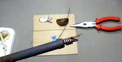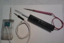
To work, you will need:
- a soldering iron with a thin sting;
- fusible solder;
- copper wire coated with varnish insulation (PEV, PEV-2 or similar). For power buses, a wire with a diameter of about 1 mm will be required, and when choosing a wire for inter-element mounting, you should be guided by the ability to easily give it the desired shape;
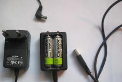
- DC power supply with a voltage of 5 ÷ 15V;
- tweezers and scissors or nippers;
- a small piece of plastic for a clip for LEDs and a drill with a drill. The size of the drill must be equal to the diameter of the emitter of the LED.
Parts used:
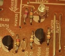
- .
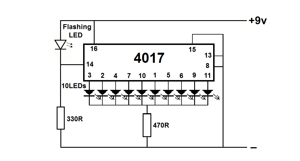
- two resistors with a resistance of 330 ÷ 470 Ohms;
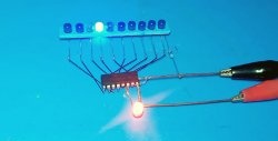
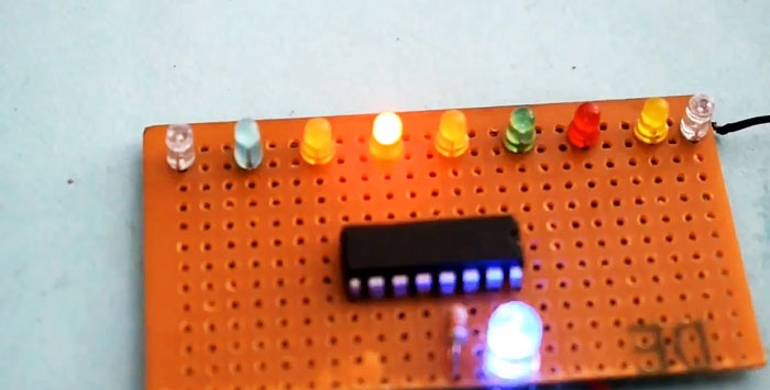
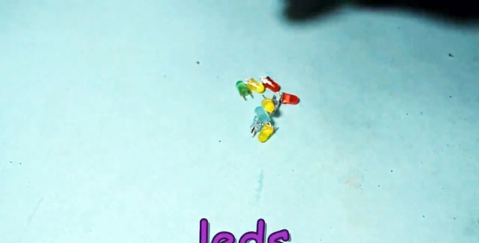
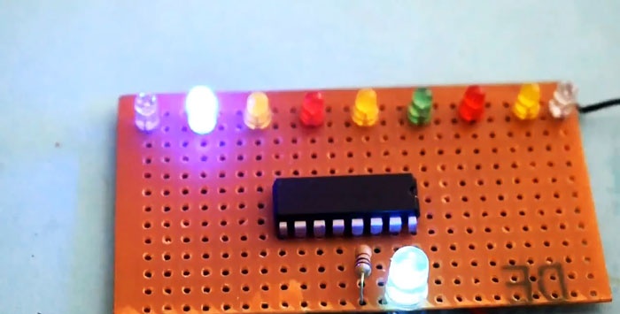
- 10 ordinary LEDs to indicate the signal level at the decoder outputs;
- . This is a relatively recent type of LEDs containing a radiating element and a circuit for controlling its operation. As a rule, in its marking after the numbers contains the letter "B". In this design, it performs the function of a control pulse generator.
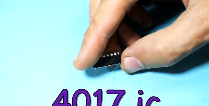
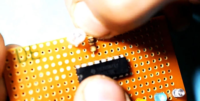
For ease of assembly, we recall the pinout of the microcircuit and LEDs.
Assembly sequence:
1. We make a holder for LEDs according to the technology available to you. It is important to note that all holes should be drilled before the plate is finalized. It will be more convenient to mark the centers of the holes and the risk of breakage during drilling and stripping will be minimal;
2. We form conclusions of signal LEDs, bending them in opposite directions;
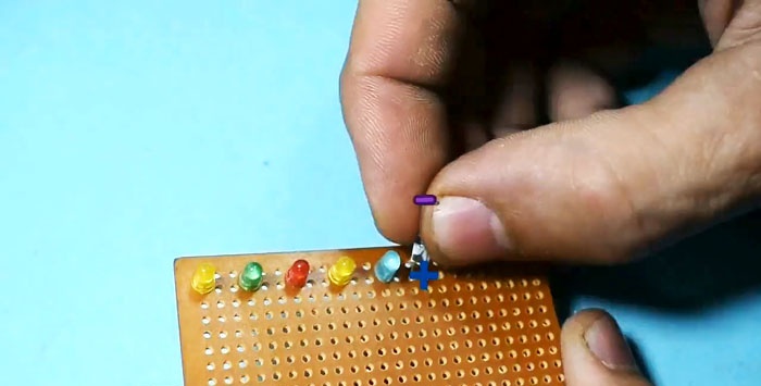
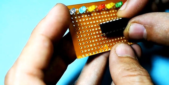
3. Install all 10 LEDs in the holes on a pre-made clip. It is important to observe the polarity so that the anodes and cathodes are located uniformly;
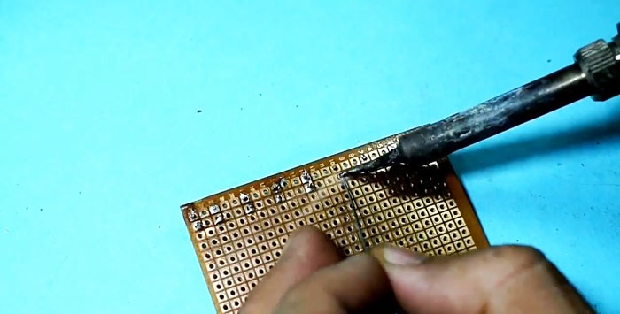
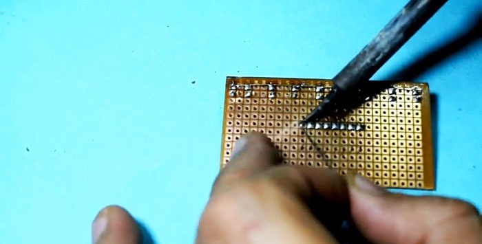
4. Tin a piece of thick copper wire, on a plot of length equal to the length of the holder;
5. Solder to it all the cathodes of the LEDs. It is important here not to overheat the soldering spots. You can use tweezers from the side of the LED as a heat sink during soldering;
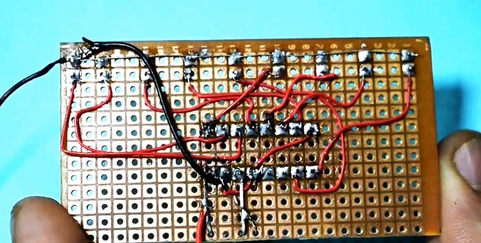
6. We cut off the unused parts of the LED leads with scissors or nippers. This completes the assembly of the ten-element indicator, which we will now connect to the decoder chip;
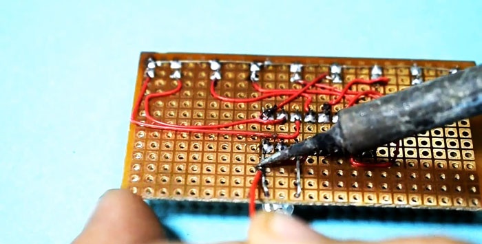
7. Cut off a piece of thin copper wire measuring 4-5 cm and tin both ends to a length of 3-5 mm. Pre-tinning will speed up soldering and prevent overheating of the LED and microcircuit during installation;
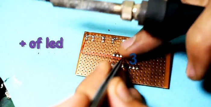
8. Solder this conductor to the anode of the extreme indicator LED, and then to the third pin of the microcircuit. Thus, we connect the pin Q0 of the microcircuit to the anode of the first LED;
9. Now we have more or less rigidly connected the microcircuit and the clip with LEDs, which makes it much easier to conduct subsequent installation;
10. We carry out serial connections with pieces of insulated wire of the appropriate length:
- pin 2 (Q1) - anode 2 of the indicator LED;
- pin 4 (Q2) - anode 3;
- pin 7 (Q3) - anode 4;

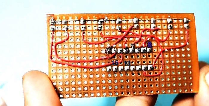
11. We bend into the case and solder the terminals 8, 13 and 15 of the microcircuit with a pre-tinned thick wire, which will act as a negative power bus. It should protrude from the microcircuit by about 5-8 cm for convenient connection to a power source;
12. We connect insulated conductors, bending them so that they do not touch each other:
- pin 1 (Q5) - anode 6;
- pin 5 (Q6) - anode 7;
- pin 6 (Q7) - anode 8;
- pin 10 (Q4) - anode 5;
- pin 9 (Q8) - anode 9;
- pin 11 (Q9) - anode 10;
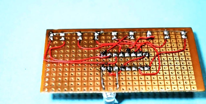
13. Solder between the terminals of the microcircuit 16 and 14 a flashing LED with the correct polarity: the anode to the 16th pin, and the cathode to 14;
14. We use the LED leg soldered to the 16th pin of the microcircuit as a place for soldering the positive power bus. Here we solder a piece of thick copper wire;
15. Between the wire bus connecting all the cathodes of the indicator LEDs and the negative power bus connecting the terminals 8, 13, 15 of the microcircuit, solder a 470 Ohm resistor;
16. Between the pin 14 of the microcircuit and the negative bus, solder a 330 Ohm resistor;
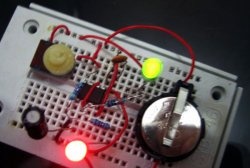
17. Check the assembled structure for short circuits and apply power to the circuit.
Conclusion
The described model allows you to visually study the operation of the counter-decoder, but does not fully disclose all of its capabilities. The values of the load resistors do not affect the operation of the circuit and can be changed. The proposed assembly sequence is subject to change at your discretion.