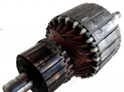
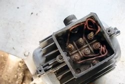
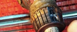
An electric motor consists of two parts: a stator and a rotor. The rotor (also called the armature) is the most complex part. It consists of a shaft with a magnetic core in which the winding is laid. The ends of the winding are connected to the plates (lamellas) of the collector.
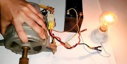
Let's start with diagnostics. The main device we need is multimeter.
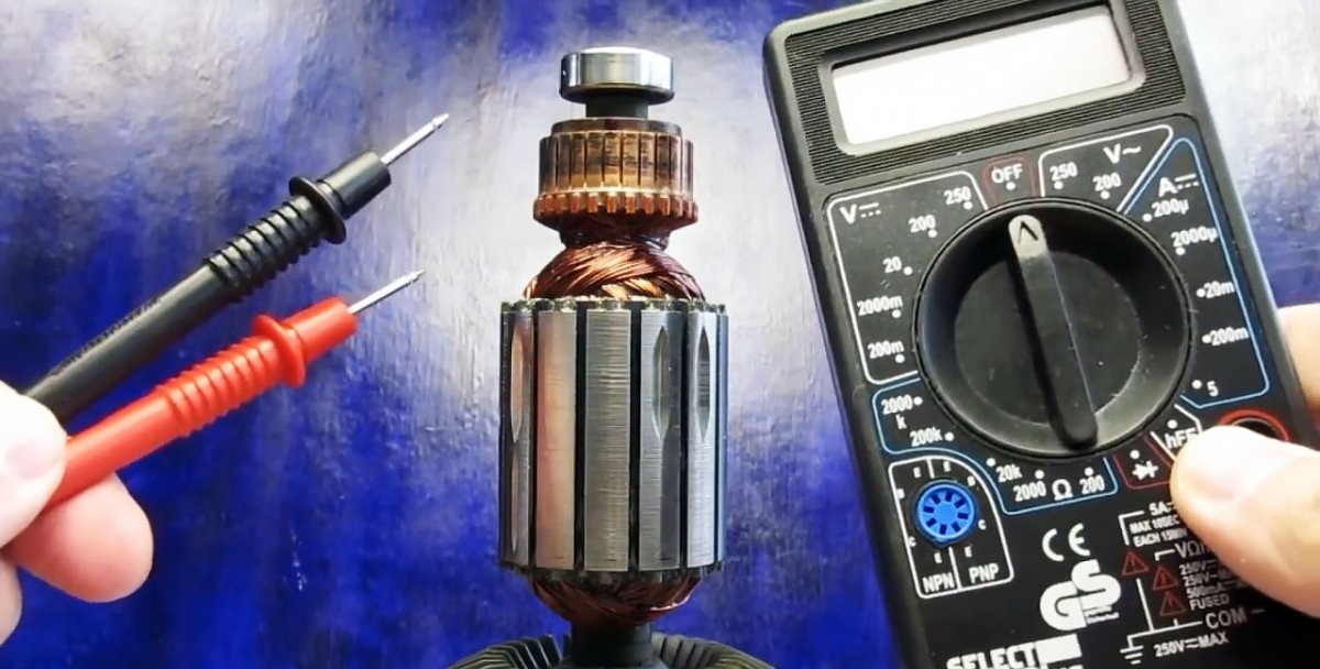
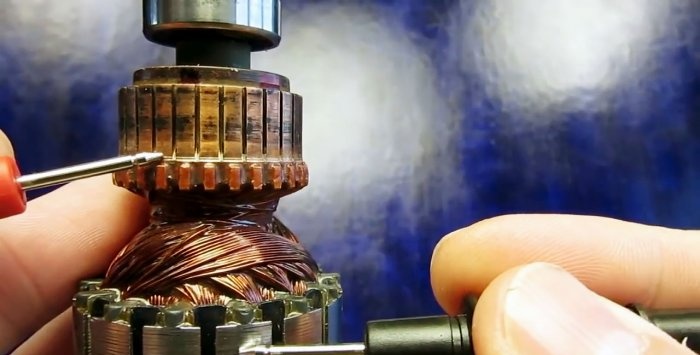
First, let's disassemble the electric motor and remove the armature. It needs to be examined. Often winding damage is visible to the naked eye. If the broken wires and the short circuit are not visible, we carry out three tests.
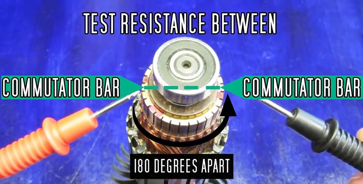
1. 180 degree test
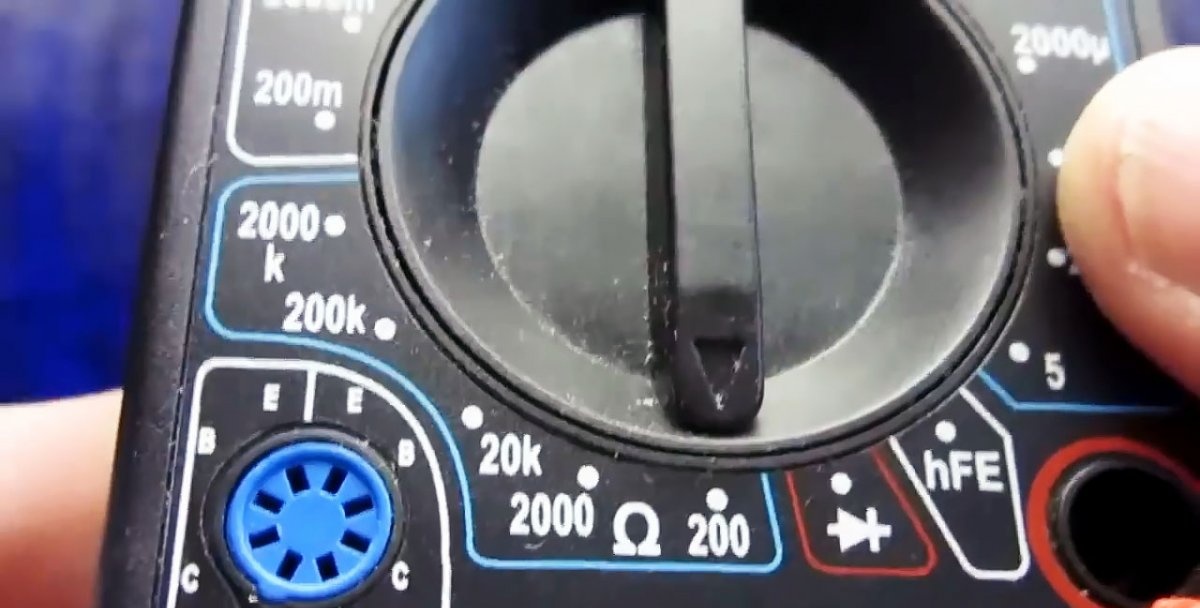
- Multimeter set to resistance measurement mode, measurement limit 200 Ohms.

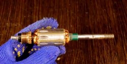
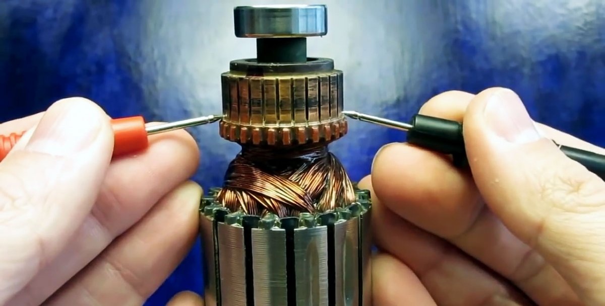
- We connect the probes to two exactly opposite contacts of the collector. These two points are 180 degrees apart.
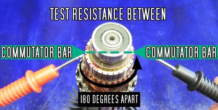
- We measure resistance. We remember or write down.

- Next, we take measurements in a circle, between the remaining opposite plates.

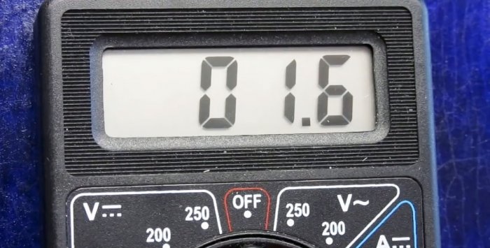
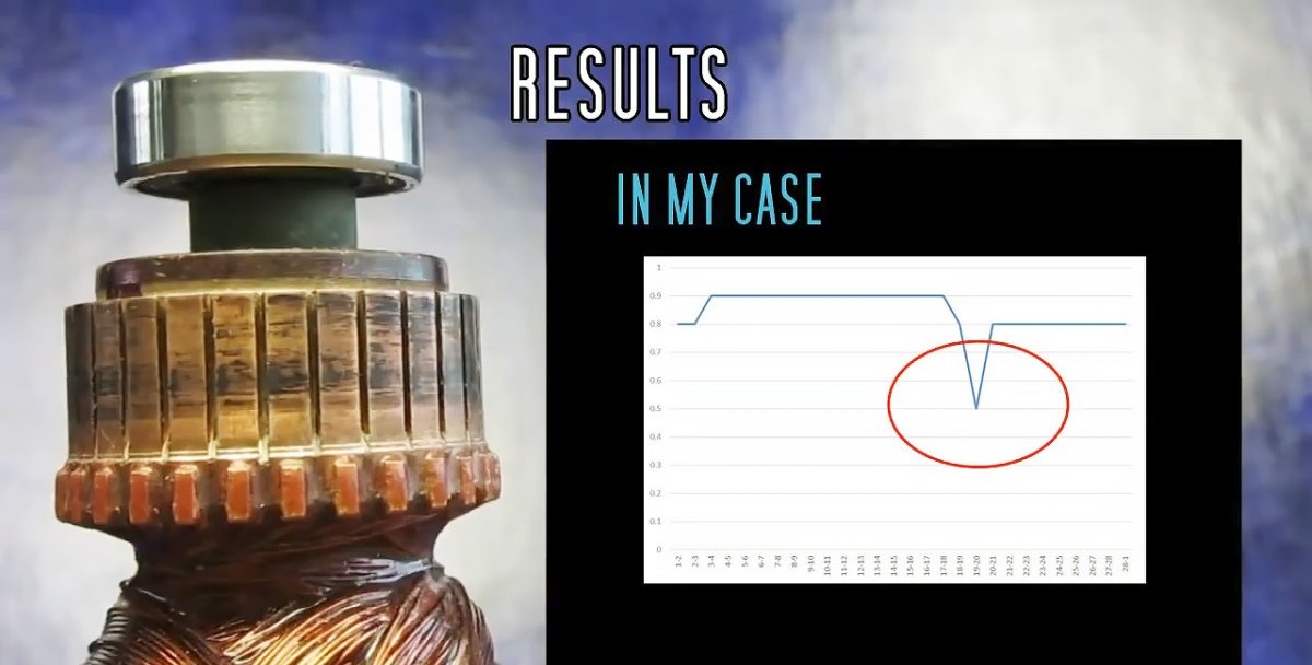
Let's summarize. The resistance values themselves are not interesting to us. The main thing is that they are the same. That is, if multimeter during the first measurement showed, for example, a value of 1.5 Ohms, then there should be the same resistance between the remaining opposite plates. If the resistance between some points is greater than ̶̶, then there is a break in this winding. If the resistance, on the contrary, is less, there is a short circuit.
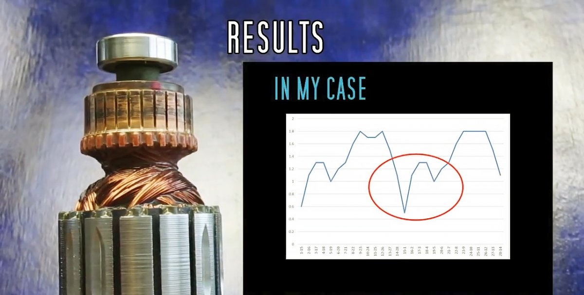
The graph clearly shows an internal short circuit in one of the windings.
2. Testing adjacent contacts
- The device remains in the same position - resistance measurement, limit 200 Ohm.
- Probes multimeter connect to two adjacent collector plates.
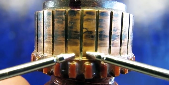
- We take a measurement and remember the result.
- Next, we take measurements between the next pair of contacts. And so on, in a circle.
- Let's compare the results.


In this test, as in the previous one, the main thing is equality of values. And, just like in the previous test, an increase in resistance indicates a break in the winding wire, and a decrease in resistance indicates a short circuit.
The graph shows an internal, interturn short circuit in one of the windings.
3. Checking the short circuit to the body
- Multimeter set to resistance measurement mode ̶̶ 200 Ohm.
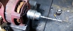
- We place one probe of the device on the collector plate, the second on the armature body (shaft or magnetic circuit).
- We take measurements one by one between each lamella and the body.

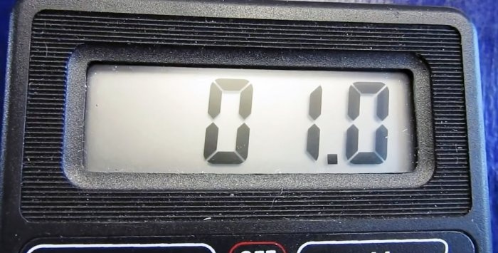
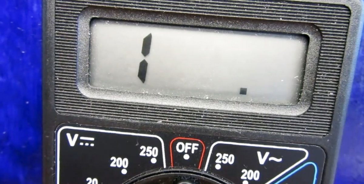
If the multimeter shows “1”, there is no short circuit to the housing. If it shows any values, or “0” and emits a beep, then the insulation is broken.
Test results
The motor armature is operational if:
1. The resistance between all opposite contacts is equal.
2.The resistance between all adjacent contacts is equal.
3. The resistance between the collector plates and the housing is equal to infinity “1”.
Recommendations
Electronic multimeters, especially for household use, have some error. Therefore, it is better to use a pointer device. If there is none, it is advisable to determine and take into account the error in measurements. This is done as follows:
- in resistance measurement mode, with a limit of 200 Ohms, connect the probes together;
- if the instrument reading is “zero” there is no error;
- if there is some other number instead of zero, this will be an error.
Let's say the multimeter shows 0.1 Ohm. This means that in the first and second tests, a resistance difference of less than 0.1 Ohm is not considered damage.
Safety precautions
When checking the rotor, the following safety precautions must be observed:
- Before disassembling, disconnect the electric motor from the network;
- A damaged armature may have sharp edges, torn commutator plates, or damaged wires sticking out, so use work gloves.