Basic materials:
- steel corner 20x20 mm;
- shaft on aluminum support SBR20;
- carriages on linear bearings for the SBR20 shaft – 12 pcs.;
- steel sheet 10 mm;
- corner 30x30 mm;
- long pin M10;
- steel sheet 3 mm;
- corner 40x40 mm;
- four-jaw lathe chuck;
- bearings in a housing with claws – 3 pcs.;
- shaft for bearings with claws;
- pulley on the shaft;
- electric motor with pulley;
- drive belt;
- tool holder and cutters
- M8 bolts.
Making a lathe
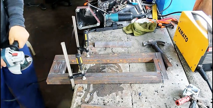
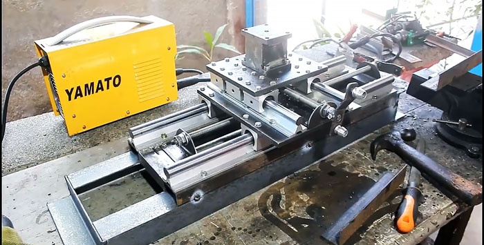
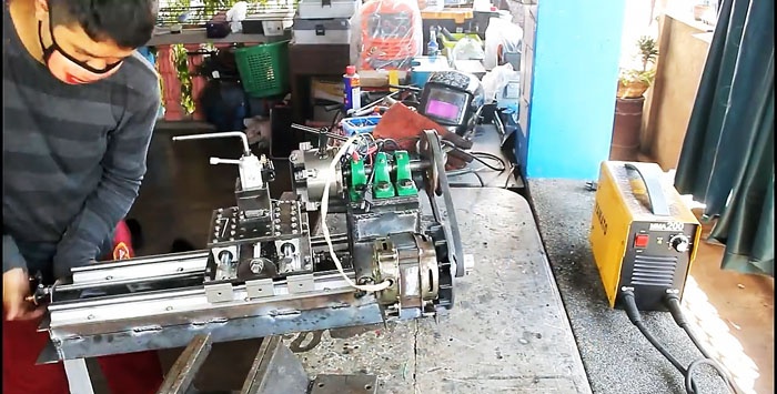
The machine frame is welded from a 20x20 mm corner, as in the photo. The top plane of the finished part must be sanded in order to be able to attach the rest of the equipment evenly.
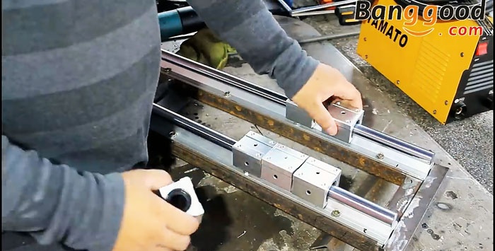
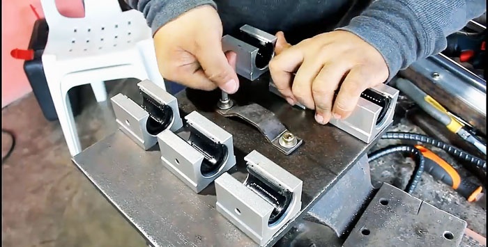
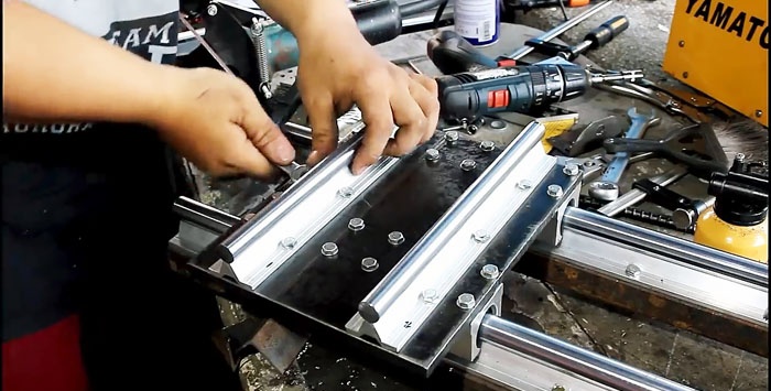
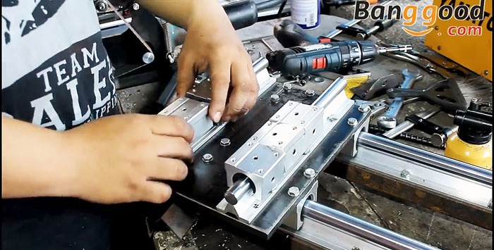
2 longitudinal slides made of a shaft on an SBR20 aluminum support are screwed along the frame. They are equipped with 3 carriages on linear bearings.

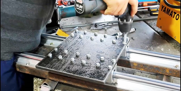
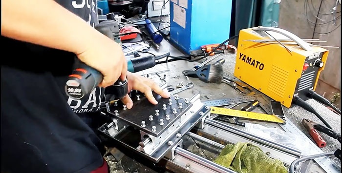
A base plate is cut out of 10mm sheet steel, which will be mounted on the carriages. It is screwed with 24 bolts, 4 for each carriage.
Next, you need to secure the feed shaft, which will move the platform along the machine. For this, a long pin with a diameter of 10 mm is used. It is attached to the ends of the machine on screwed supports made from a turned corner 30x30 mm.
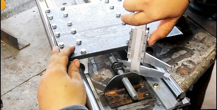
To attach the carriage platform to the shaft, you need to make a protrusion on the back of its plate. To do this, a bracket is bent from a 3 mm steel strip. It needs to be screwed to the stove as in the photo.
Next, the made bracket is welded to 3 M10 nuts screwed onto the feed shaft from a stud. Now, when the shaft rotates, the platform moves along the machine.
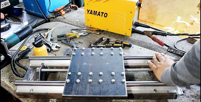
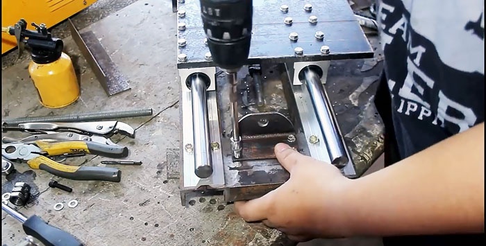
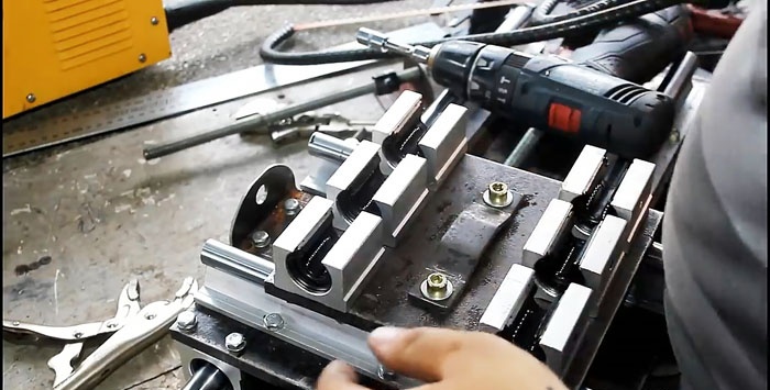
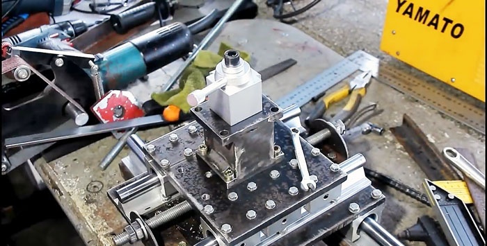
2 transverse slides from the same shaft are attached to the finished platform on an SBR20 aluminum support. Each skid is equipped with 3 carriages.
A steel plate 10 mm thick is screwed on top of the carriages with 24 bolts.
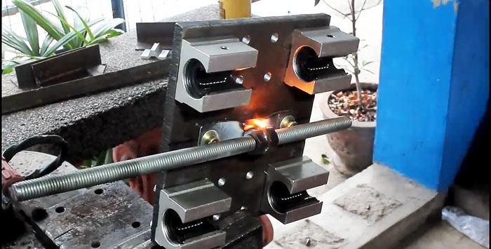
For lateral movement of the platform, the installation of a feed shaft is also required. It is made from the same M10 pin according to a similar principle as the lower platform mechanism. To do this, 2 supports are made from a turned corner 30x30 mm and a bracket from a 3 mm strip, which is welded to 3 M10 nuts on the shaft.
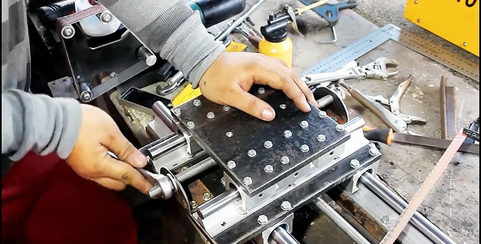
Next, you need to make a cube platform for the tool holder. Its top and bottom parts can be made from 10 mm sheet steel, and the sides from 3 mm sheet. Since there is a load on this unit, it should be reinforced with another side insert made of 3 mm sheet steel. A central hole is made in the upper part of the resulting cube, into which a thread is cut. It is used to attach the factory tool holder.
The base of the tool holder is screwed to the small platform of the machine using 4 bolts.
Handles are installed on the longitudinal and transverse feed shafts of the machine.
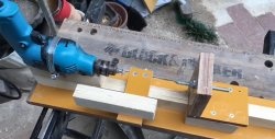
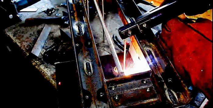
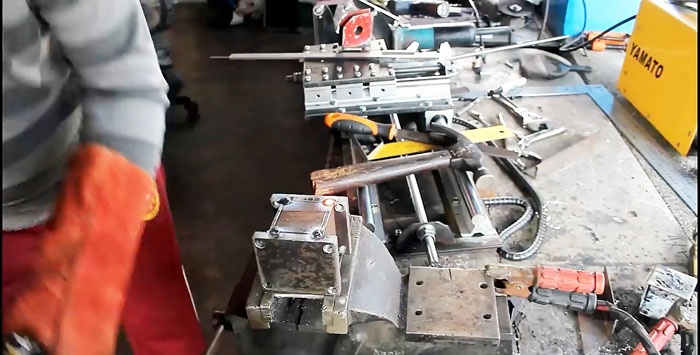
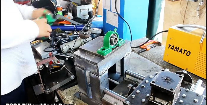
A 40x40 mm corner is welded along the perimeter of the base of the machine from a 20x20 mm corner. The longitudinal parts of the new angle are made longer to provide a base on the left for securing the spindle.

A 40x40 mm corner is welded onto the resulting base, as in the photo. The resulting structure is strengthened with inserts, since it will be subject to a strong deformation load.
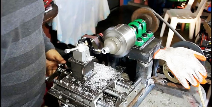
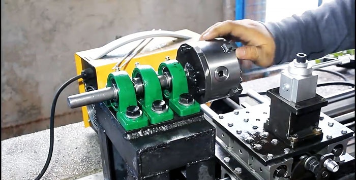
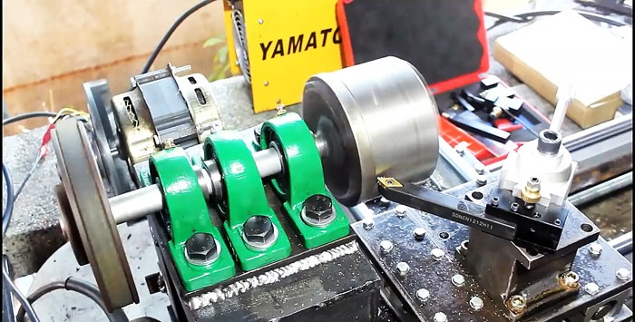
A platform made of 10 mm sheet steel is welded on top of the resulting frame. 3 bearings in a housing with claws are attached to it. A steel shaft is inserted into the bearings.
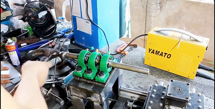
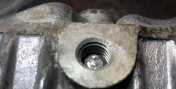
A circle corresponding to the diameter of the factory four-jaw chuck is cut out of 10 mm sheet steel. A large hole is made in its center corresponding to the diameter of the shaft. The manufactured part is mounted on a shaft mounted on bearings
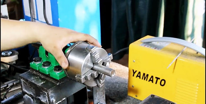
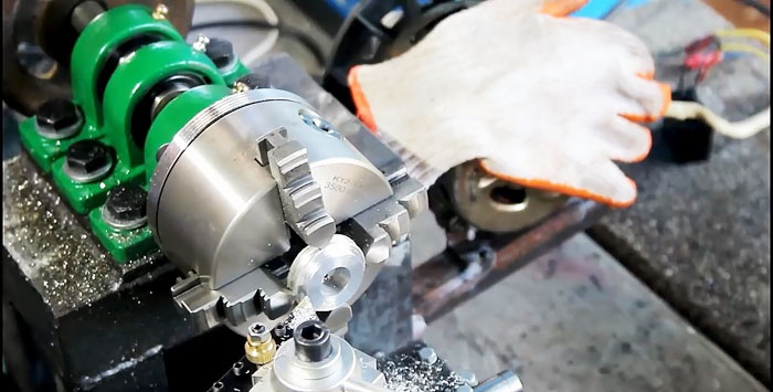
Having installed and clamped the four-jaw spindle on the shaft, you need to press the cut circle against it and tighten it with the chuck using 3 bolts. This allows the circle to be balanced before welding it to the shaft.
Next, you need to remove the four-jaw spindle and cut off the excess part of the shaft along the line of the welded circle. The lathe chuck is installed back into its seat and clamped with 3 bolts.
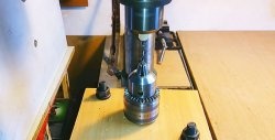
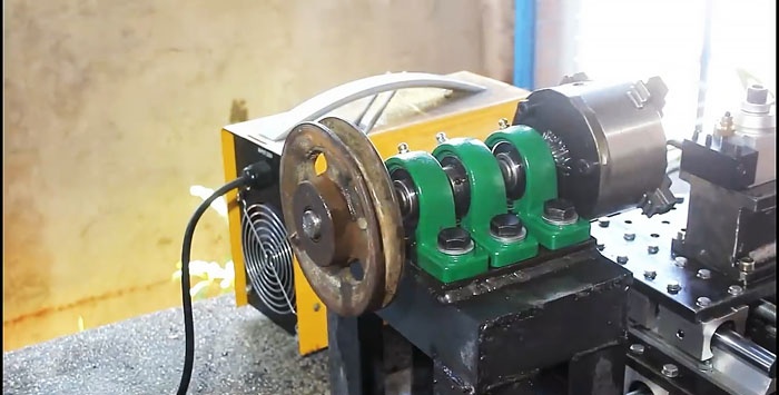
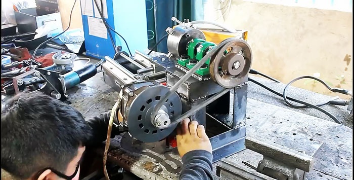
A pulley is attached to the reverse side of the shaft.
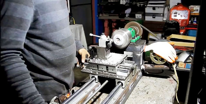
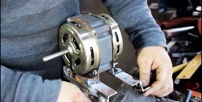
For the existing electric motor, a frame is welded from a 20x20 mm corner. A small pulley is installed on the motor.
After this, by tensioning the belt between the pulleys, you need to place the engine on the base of the spindle shaft bearing platform.The electric motor frame must be made in such a way that it is possible to adjust the belt tension after welding it.
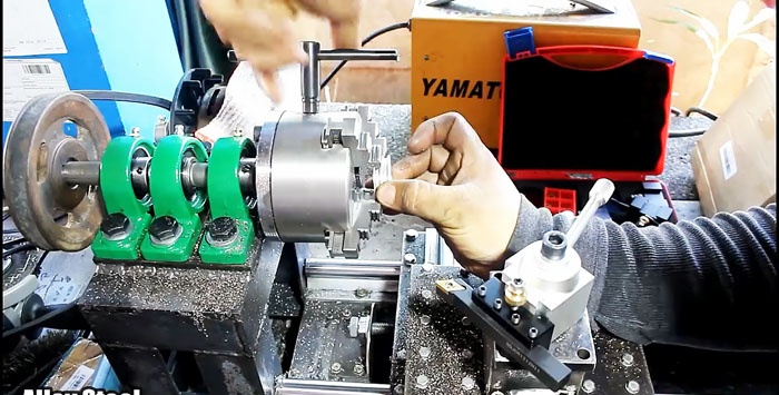
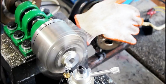
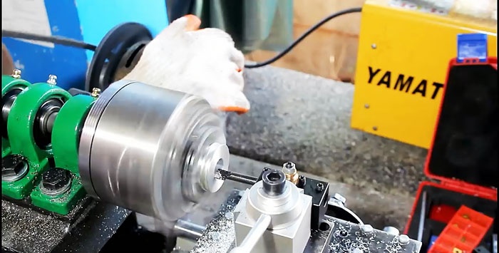
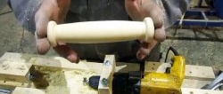
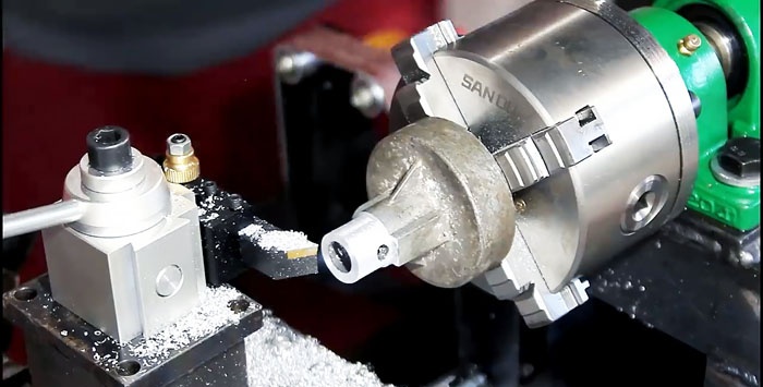
Having secured the cutter in the tool holder of the machine, you can already use it for its intended purpose. This design allows you to get the cutter close to the circle on which the spindle is attached in order to grind it, making it more accurate.
The resulting machine has the ability to be modernized, for example, installing a tailstock, which will allow it to perform more serious tasks. This is a fairly expensive project, but it will cost less than a factory lathe.