DIY do it yourself
Master classes, instructions, useful tips, recipes.
» » »Radio microphone - radio bug
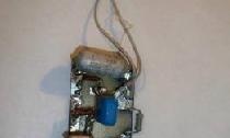
This is perhaps the most popular simple and common radio bug or radio microphone circuit. A minimum of detail and a minimum of time is required to build this baby. Due to the use of a microphone from Chinese products, the sensitivity of this device is very high. This bug is not whimsical in manufacturing, not demanding on a power source. Of course, along with the obvious advantages of this circuit, there are also disadvantages, the main one, in my opinion, is a large frequency drift when changing the power supply, but this battery is not critical when this radio microphone is powered by batteries.


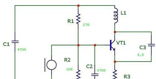
This radio beetle works according to the capacitive three-ton scheme. The oscillation circuit is tuned to a frequency of 90 MHz. But with ease you can choose any frequency from the interval 30 - 120 MHz.


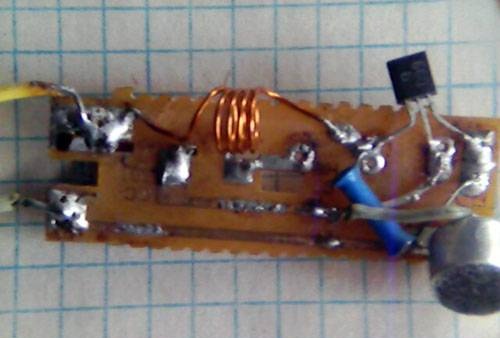
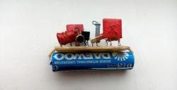
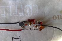
Transistor KT660B. The coil is a frame with a diameter of 7mm, see the rest for the rest.
The transistor can be any, even low-frequency.
 
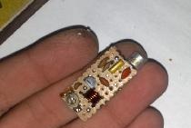
With good parts, the bug starts working immediately. It is only required to select the desired frequency.


It is very simple to determine the operation of a bug without a receiver. To do this, measure the current consumption, and then short-circuit the oscillating circuit, if the current consumption has changed, then the device is working.

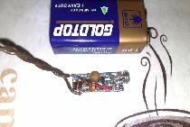
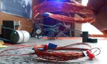
The antenna is connected to the collector of the transistor, it can burn to be a piece of wire up to a meter long. It is better to connect the antenna through a 10-15 pF capacitor.

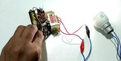
I forgot to draw, the power is connected to the capacitor C1, the top pin is in the plus circuit. Power supply 1.5 - 15 volts.
come back
Comments (19)
  1. purgen2013
    #1 purgen2013 Guests January 4, 2012 11:27 p.m.
    0
    applause Wow cool, more of such material would be laid out)))
  2. NOTFRONT
    #2 NOTFRONT Guests January 5, 2012 11:36
    0
    Wow cool, more would be sent such material.
  3. wefl
    #3 wefl Guests January 6, 2012 2:45 p.m.
    1
    which of these transistors is better to put
    ct315
    kt361b
    kt837a
    ct3102
  4. NOTFRONT
    #4 NOTFRONT Guests January 6, 2012 3:02 p.m.
    1
    anyone will go, pick it yourself and find out which one is better! cool
  5. cat
    #5 cat Guests February 19, 2012 23:39
    0
    the question is, what is the transmission distance? And will the fm receiver be able to receive the signal?
  6. dima1996ru.dima
    #6 dima1996ru.dima Guests February 26, 2012 16:40
    1
    and what to take
  7. Volf
    #7 Volf Guests March 3, 2012 18:28
    3
    You can receive on a regular am-fm receiver in the range of 63-78 or 88-108 MHz, depending on the transmitter settings. The frequency is roughly set by selecting C3, and finely by pushing / shifting the turns of the coil.

    If you are not too lazy and add a third coil, as shown in the figure, then you will be spared from leaving the frequency when approaching the transmitter or when touching the transmitter.
  8. Volf
    #8 Volf Guests March 3, 2012 18:43
    1
    Quote: wefl
    which of these transistors is better to put
    ct315
    kt361b
    kt837a
    ct3102


    You can put any of these transistors.Only for KT361 it is necessary to change the power polarity, and for the 837th, increase the current of the base divider, for example, R1-15k, R2-4.7k. 315 and 3102 - no change. Just less power will come out.
  9. Glory
    #9 Glory Guests March 29, 2012 16:26
    1
    But is the s8050 transistor suitable for this circuit?
  10. Sadat
    #10 Sadat Guests January 8, 2013 03:49
    0
    Is the s9018 transistor suitable?
  11. Artyom 111
    #11 Artyom 111 Guests January 13, 2013 19:34
    0
    What transistors can the circuit work with?
  12. Artyom 111
    #12 Artyom 111 Guests January 31, 2013 18:00
    0
    can lay out a list of details
    Tell me where can I get them? ? ?
    : recourse:
  13. coma34
    #13 coma34 Guests April 25, 2013 14:39
    0
    Why do you need a list of parts if everything is indicated on the diagram; how many resistors, how many transistors, what kind of power, etc. And you can get them in any store with radio parts or on the market, usually grandfathers sell them .. Well, or, unscrew, solder them from the boards from different devices ..)
  14. Maksim
    #14 Maksim Guests September 25, 2013 19:06
    0
    Cool: bully: and most importantly safe!
  15. Artyom
    #15 Artyom Guests October 10, 2014 20:31
    0
    and the CT 368 transistor will do ?? and C3 there tuning ??
  16. Anatoliy
    #16 Anatoliy Guests October 23, 2014 8:25 PM
    0
    Can I ask a question and can the kt908a transistor be soldered?
    : wassat:
  17. Willow
    #17 Willow Guests December 4, 2014 17:02
    0
    Kt814v will do?
  18. bean
    #18 bean Guests February 24, 2015 15:57
    0
    Tell me what is the rating of capacitors
  19. Kostya
    #19 Kostya Guests April 11, 2015 11:42
    1
    You have strange vibrations. circuit, where is the conder in the LC circuit?
    I don’t see the tracks on the board, if you count it, you need to parallel to the coil
    1 ----------------------------------------------------------------------------
    Coil Calculation
    Single layer coil to coil
    Frame diameter D: 5 mm.
    Wire diameter d: 0.5 mm.
    Winding length l: 5 mm.
    Number of coil turns: 4
    Coil Inductance: 0.065 μH
    2 ----------------------------------------------------------------------------
    Inductance and frequency known
    Inductance: 0.06475 μH
    Loop frequency: 90 kHz

    Loop capacity: 48296479.166 pF
    3 ----------------------------------------------------------------------------
    Inductance and frequency known
    Inductance: 0.06475 μH
    Loop frequency: 90,000 kHz

    Loop Capacitance: 48.296 pF

    Conder 48 pF. (120 and 80 pF in series)
    4700s of the base should be thrown to the plus of the circuit (power is not indicated on the circuit, + from above - from below)

Read also

Error codes for washing machines