An adjustable power supply is the right thing. In general, I think there should be a sufficient number of power supplies. It took the father, for small needs, an adjustable power supply. Having studied their deposits, a number of components were accumulated. I decided to assemble a small PSU.
What will be needed for manufacturing?
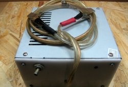
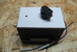
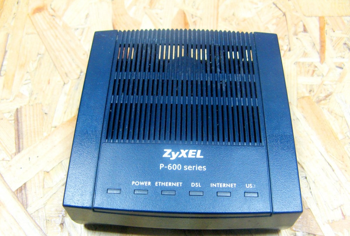
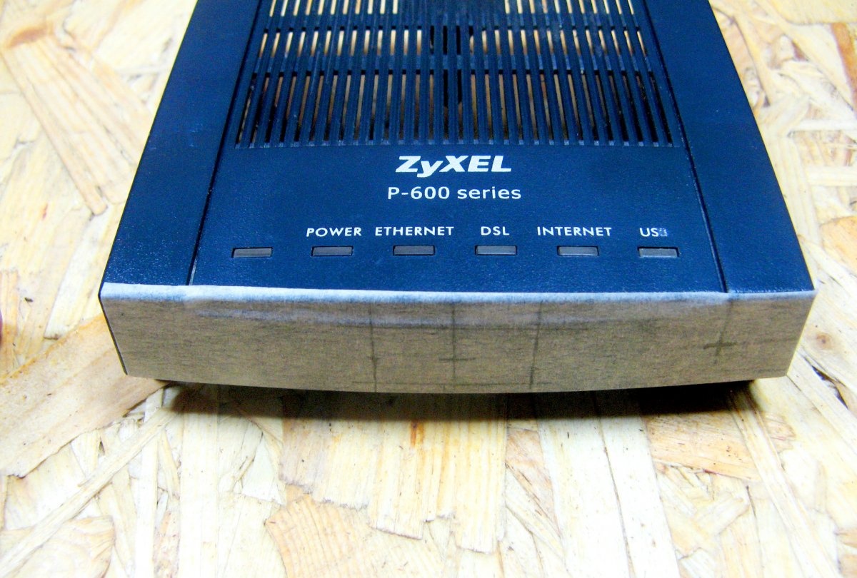
A suitable case for my venture, a box from an old modem is applicable. I will not paint windows under the LEDs. I didn’t draw the scheme, it is very simple. The mains supply will lower the mains voltage. Regulate the output voltage will .
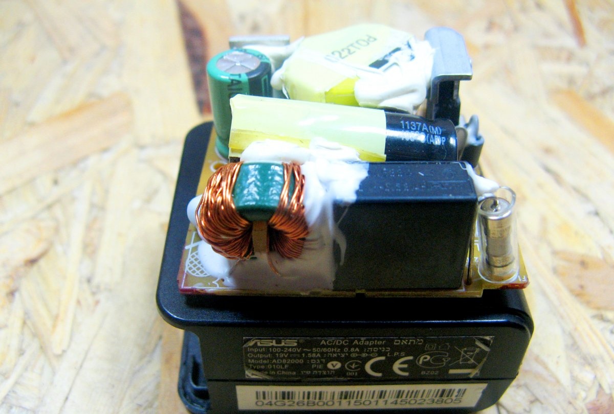
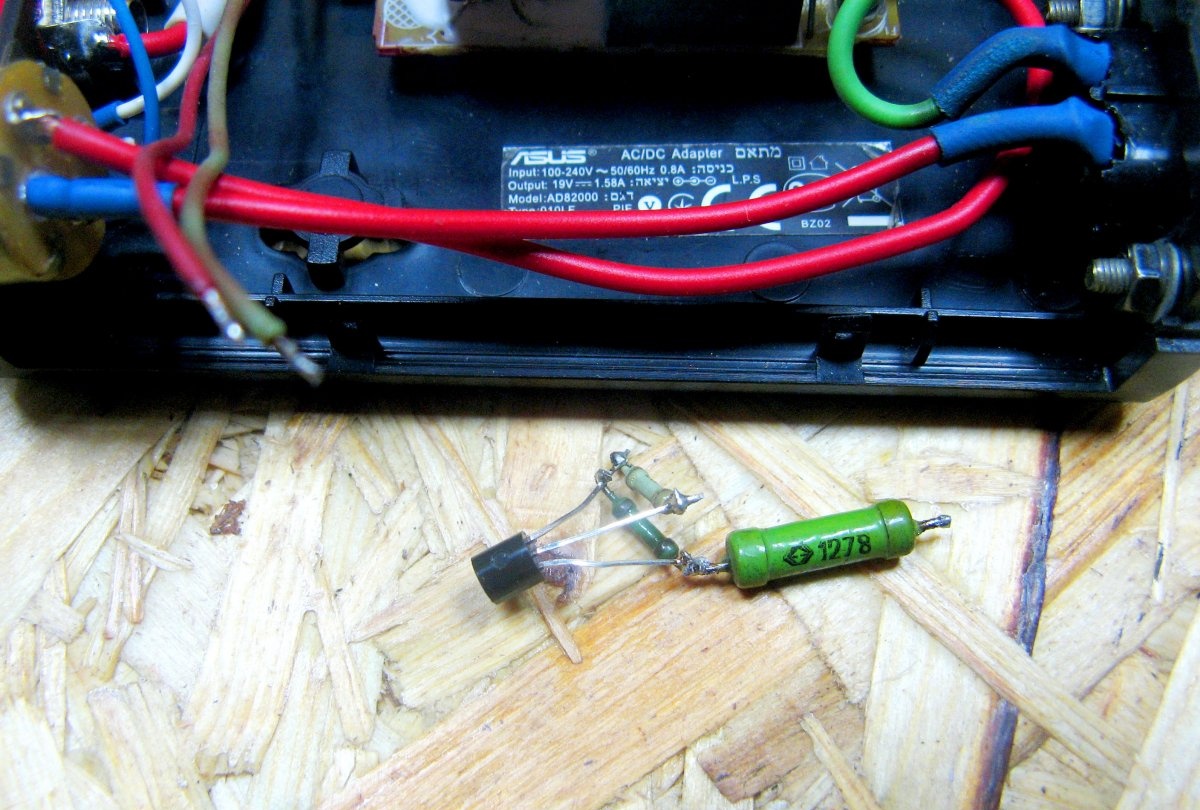
As a basis, I will use a network power supply from a netbook. It is small in size. The output voltage is 19 volts and the maximum current is 1.54 amperes.
I will regulate the output voltage using this module. It is quite reliable and cheap.
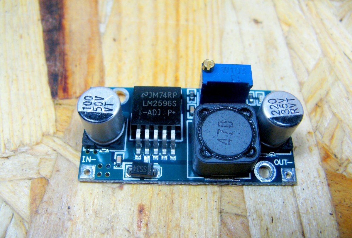
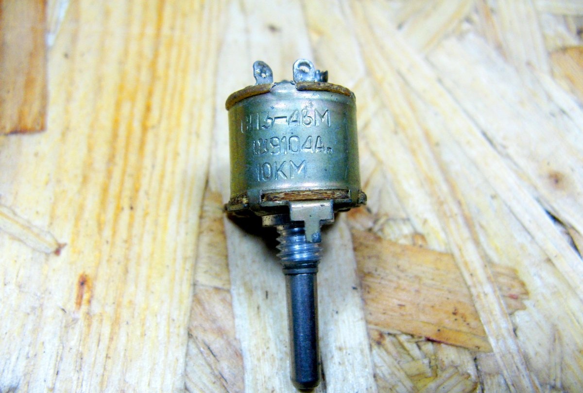
Trimmer resistor of the module, replace with the adjusting one. The resistor is combined with a switch, very convenient. It can be used without a switch, but then you need a separate switch.
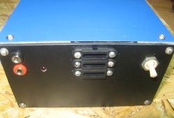
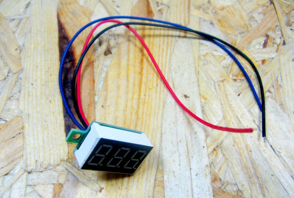
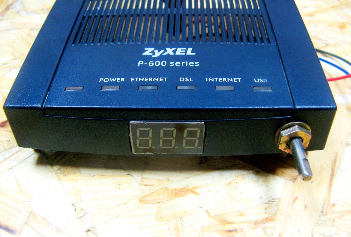
The output voltage indicator . It is compact and fairly accurate.
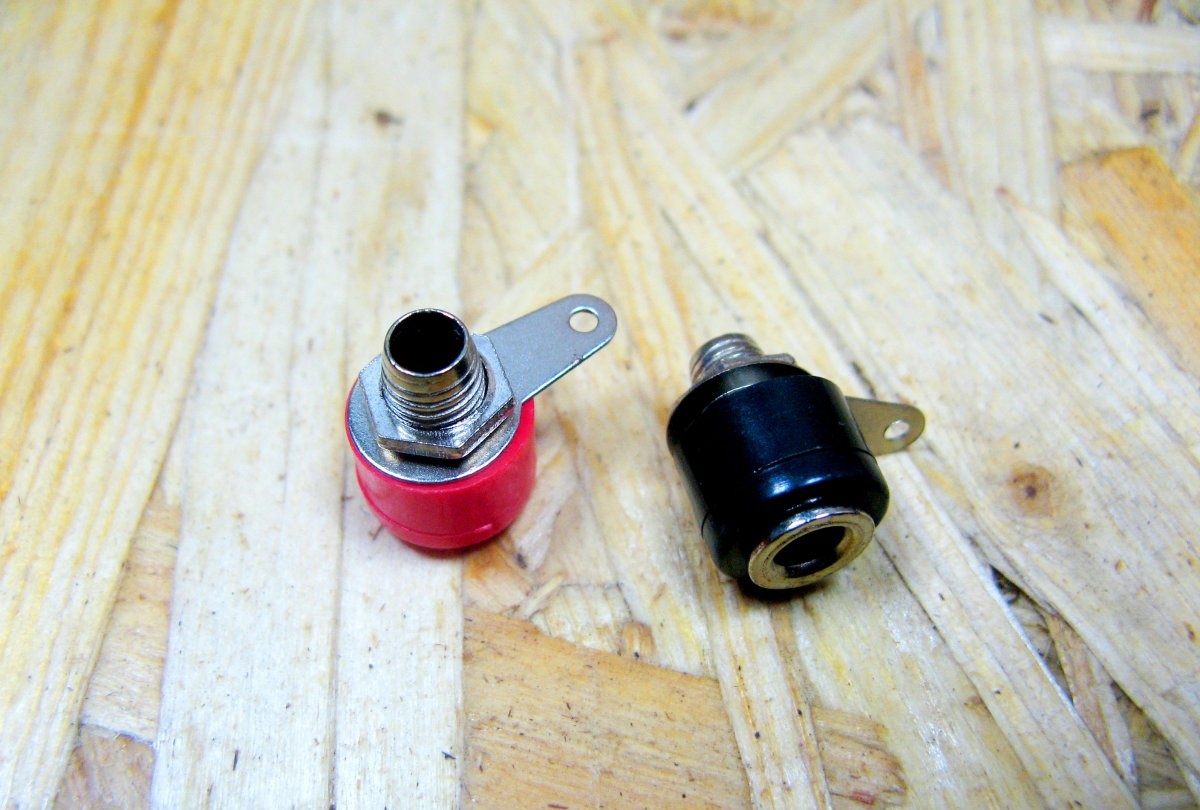
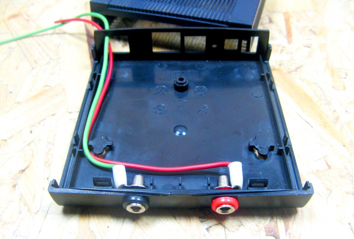
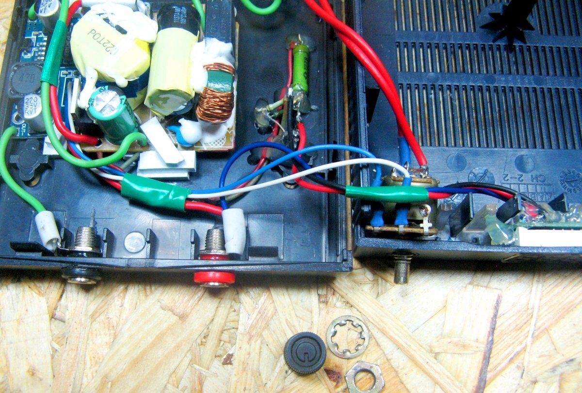
Terminals used Chinese, such as "banana". Not fundamentally, you can apply any suitable.
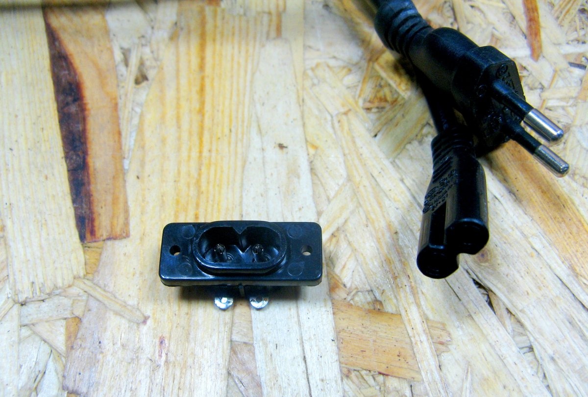
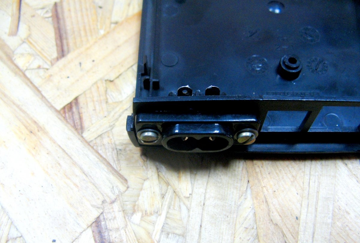
The network connector is what it is. Removed from the old flashlight.
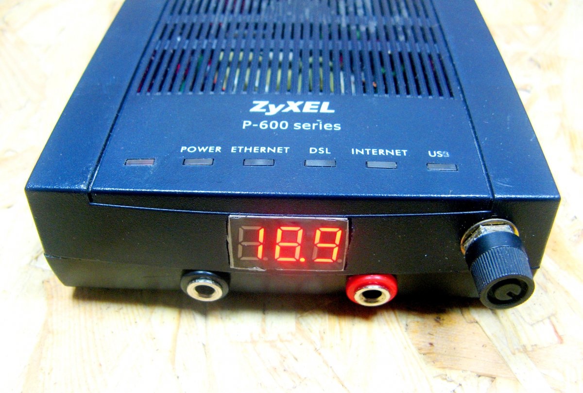
Small and adjustable DIY power supply
The first to modify the cover. It is necessary to mark the places for the voltmeter and resistor. I glue the masking tape and mark on it.
I cut the window under the voltmeter with a sharp knife. I drill a hole with a suitable drill. Trying on. The axis of the resistor was long, cut on an emery. It is also necessary to make a cut under the handle.
I install the terminals on the bottom of the case. I also fasten the wires. The wires will go to the adjustment module.
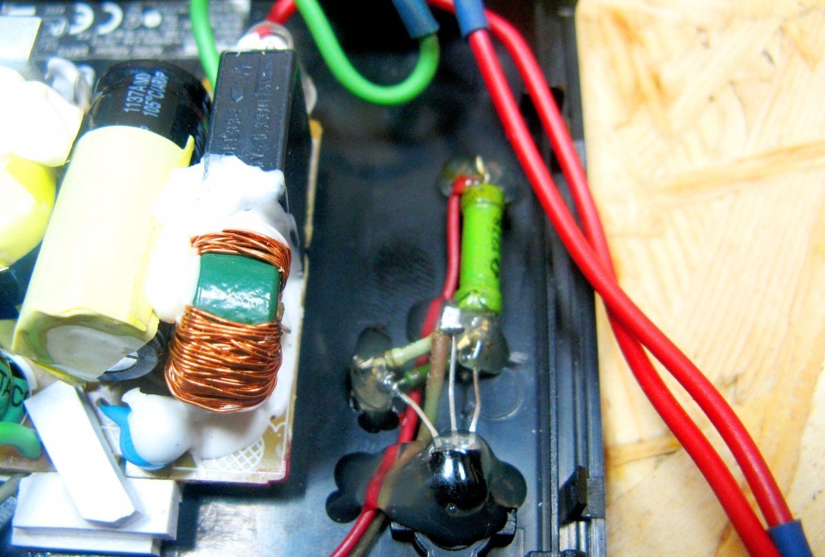
I cut the hole on the back of the case. I install the connector for connecting the power cord.
I will seal extra holes later. I’ll cover them with a piece of the printer’s cover.
I install the adjustment module and solder wires to it. Also trimmed the resistor. Instead of a soldered resistor, I soldered the wires.
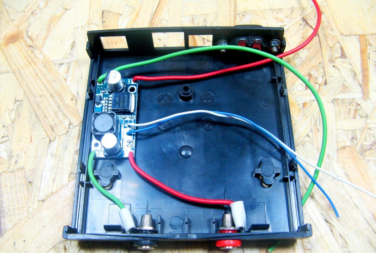
I connect the output of the netbook power supply to the adjustment module. I solder the wires to the adjustment resistor. From the network connector, I'm looking for one wire to the power supply. I tear the second one with a resistor switch.
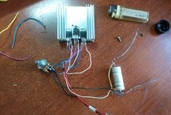
I will use a voltmeter to power . The stabilizer is assembled according to the standard scheme. I chose power at 9 volts. Calculation of resistors made in an online calculator.
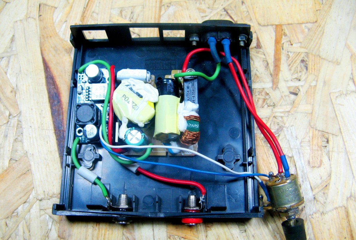
I fix the boards with PVC plastic segments. I drip the glue and apply the cut. Plastic grabs instantly. It keeps excellent.
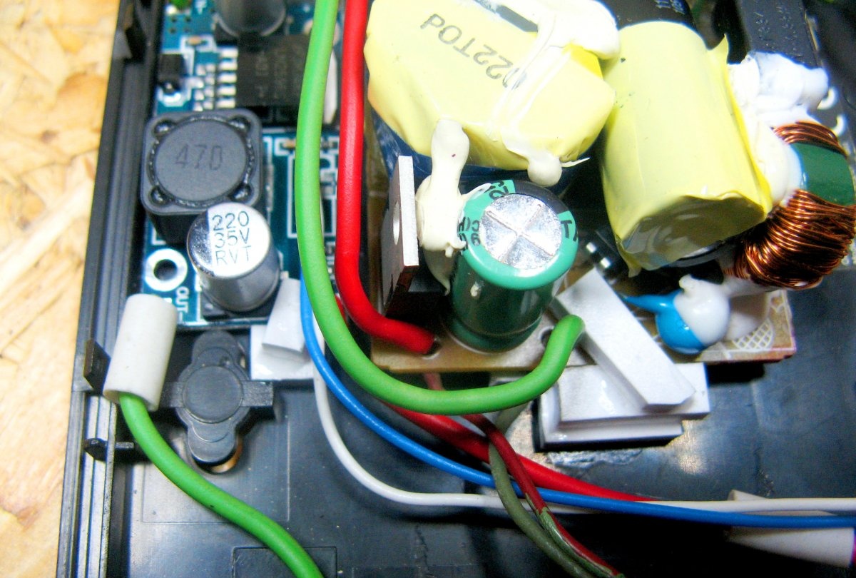
I fix the stabilizer with glue. It keeps excellent. I feed the stabilizer from the output of the main source of 19 volts.
I am soldering the wires from the voltmeter to the stabilizer. Install the adjustment resistor. I put a handle on the resistor. I connect both halves of the case and twist with a screw.
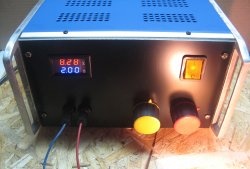
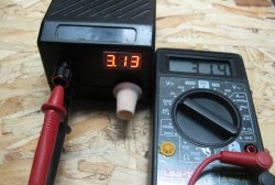
BP result
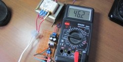
The output voltage is adjustable from 1.24 volts.
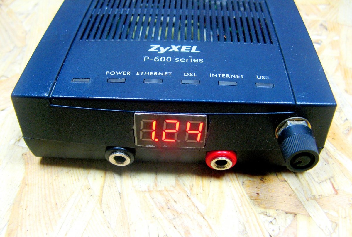
Up to 18.9 volts.
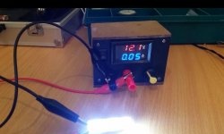
The output voltage is stable. This unit is perfect for small household needs. At least adjust the fan speed, at least adjust the brightness of the LED strip.
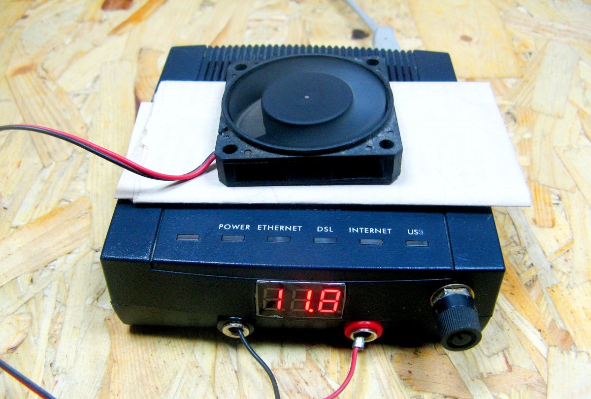
Such a small power supply with adjustment turned out. In this case, passive cooling.If you use a closed case, but you need to take care of air ventilation.