DIY do it yourself
Master classes, instructions, useful tips, recipes.
» » »Powerful do-it-yourself 12 V switching power supply
Good day, dear friends, in this article I want to share with you my experience in creating switching power supplies. We will talk about how to assemble a pulsed power supply on the IR2153 chip with your own hands.
The IR2153 chip is a high-voltage shutter driver, it builds many different circuits, power supplies, chargers, etc. The supply voltage varies from 10 to 20 volts, the operating current is 5 mA and the operating temperature is up to 125 degrees Celsius.
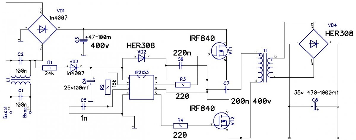
Novice hams are afraid to assemble their first switching power supply, very often resort to transformer units. At one time I was also afraid, but still I got together and decided to try it, especially since there were enough parts to assemble it. Now let's talk a little about the scheme. This is a standard half-bridge power supply with an IR2153 on board.
DIY Powerful 12 Volt Switching Power Supply

Details


Input diode bridge 1n4007 or finished diode assembly rated for a current of at least 1 A and a reverse voltage of 1000 V.
A resistor R1 of at least two watts is possible and 5 watts is 24 kΩ, a resistor is R2 R3 R4 with a power of 0.25 watts.
The electrolytic capacitor on the high side is 400 volts 47 microfarads.
Output 35 volts 470 - 1000 microfarads. Film filter capacitors designed for a voltage of at least 250 V 0.1 - 0.33 μF. Capacitor C5 - 1 nF. Ceramic, C6 ceramic capacitor 220 nF, C7 film 220 nF 400 V. Transistor VT1 VT2 N IRF840, a transformer from an old computer power supply, a diode output bridge full of four ultra-fast HER308 diodes or other similar ones.
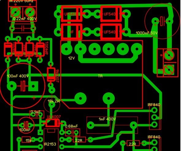
In the archive you can download the circuit and board:
[100.06 Kb] (downloads: 1122)

DIY Powerful 12 Volt Switching Power Supply

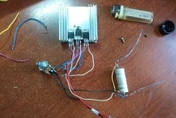
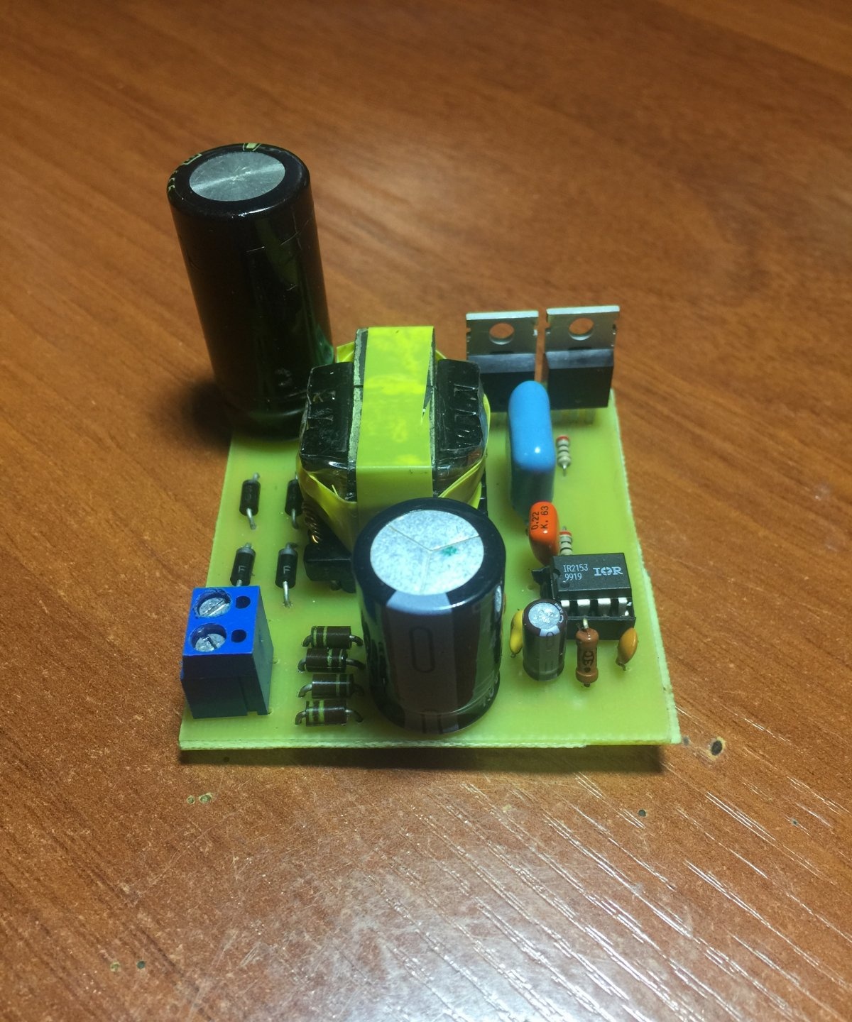
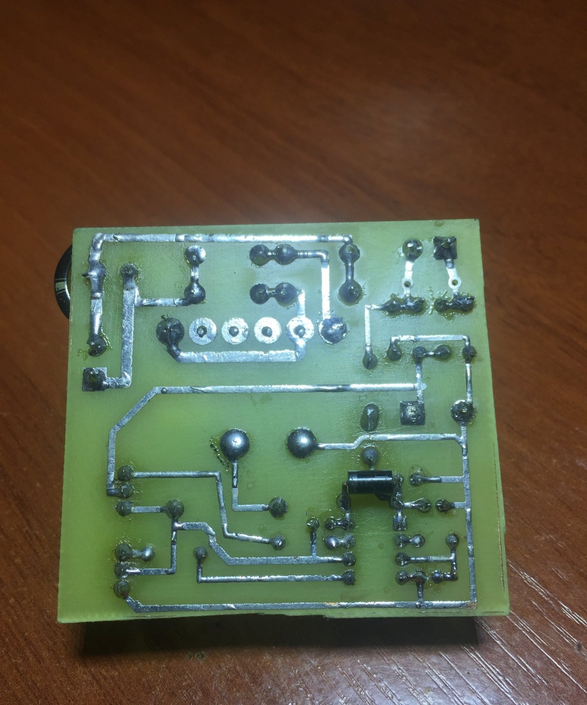
The printed circuit board is made on a piece of foil-coated single-sided fiberglass using the LUT method. For convenience, connecting the power and connecting the output voltage on the board are screw terminals.
DIY Powerful 12 Volt Switching Power Supply

DIY Powerful 12 V Switching Power Supply

12 V switching power supply circuit


The advantage of this circuit is that this circuit is very popular of its kind and is repeated by many amateur radio enthusiasts as their first switching power supply and efficiency and, to say nothing of the size. The circuit is powered by a mains voltage of 220 volts at the input there is a filter that consists of a choke and two film capacitors designed for voltages of at least 250-300 volts with capacities from 0.1 to 0.33 microfarads and can be taken from a computer power supply.
DIY Powerful 12 V Switching Power Supply

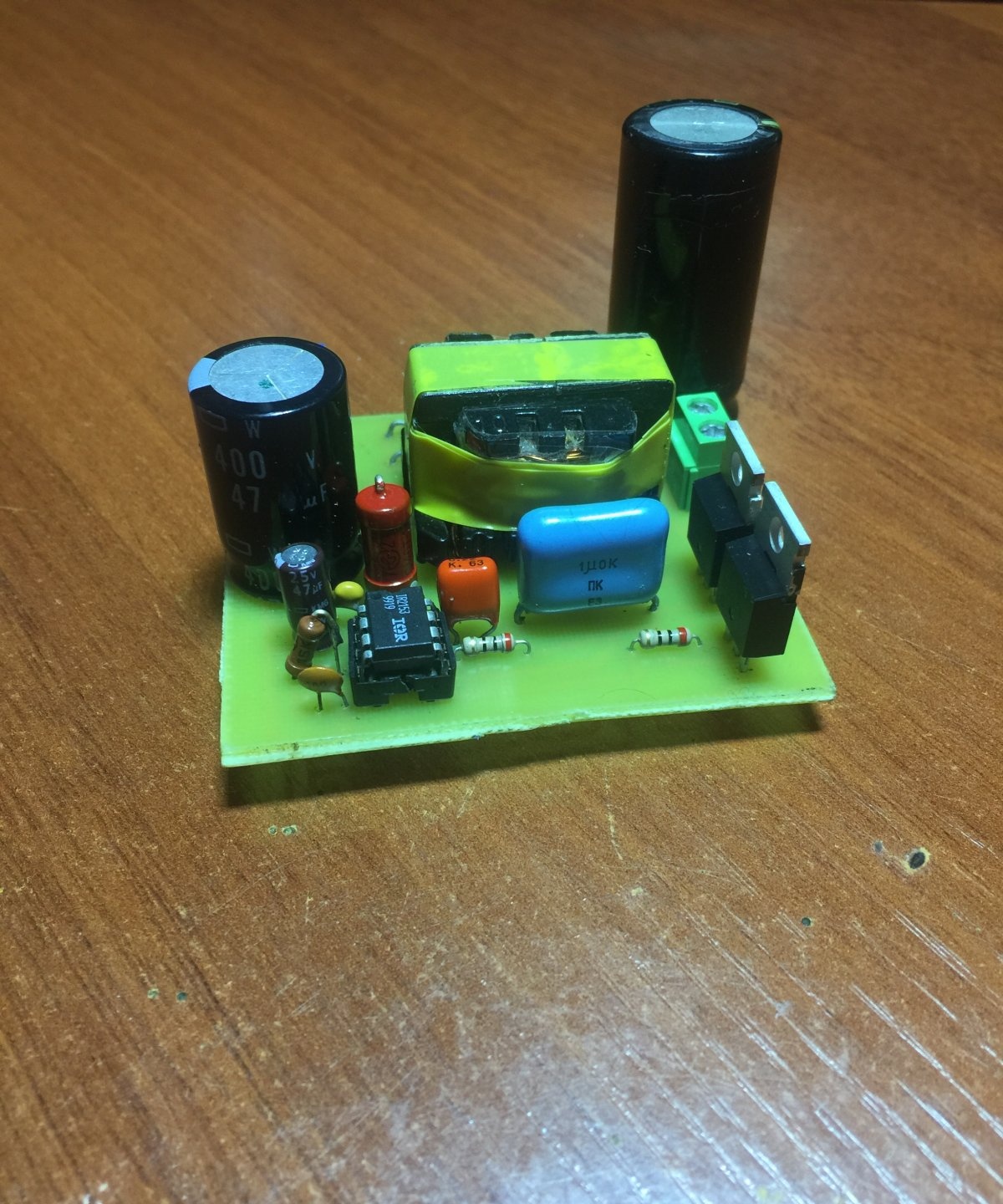
In my case, there is no filter, but it is desirable to put it. Next, the voltage supplied to the diode bridge is designed for a reverse voltage of at least 400 volts and a current of at least 1 ampere. You can put the finished diode assembly. Further, according to the scheme, there is a smoothing capacitor with an operating voltage of 400 V, since the amplitude value of the mains voltage is around 300 V. The capacitance of this capacitor is selected as follows, 1 μF per 1 Watt of power, since I am not going to pump large currents from this unit, then in my case, there is a 47 uF capacitor, although hundreds of watts can be pumped out of such a circuit. The power supply of the microcircuit is taken from the break, a power supply resistor R1 is organized here that provides current suppression, it is advisable to put at least two watts more powerful since it is heated, then the voltage is rectified by only one diode and supplied to the smoothing capacitor and then to the microcircuit. 1 pin of the chip plus power and 4 pin is minus power.
DIY Powerful 12 V Switching Power Supply

You can also collect a separate power source for it and apply according to the polarity of 15 V.In our case, the microcircuit operates at a frequency of 47 - 48 kHz for this frequency an RC circuit is organized consisting of a 15 kΩ resistor R2 and a film or ceramic capacitor at 1 nF. In this scenario, the microcircuit will work correctly and produce rectangular pulses at their outputs that are fed to the gates of powerful field keys through resistors R3 R4, their values ​​can deviate from 10 to 40 ohms. Transistors must be set to N channel, in my case there are IRF840 with a working drain voltage of source 500 V and a maximum drain current at a temperature of 25 degrees 8 A and a maximum power dissipation of 125 watts. Next, according to the scheme, there is a pulsed transformer, after which there is a full-fledged rectifier of four HER308 diodes, ordinary diodes will not work here because they will not be able to work at high frequencies, so we put ultra-fast diodes and after the bridge the voltage is already supplied to the 35 V 1000 uF output capacitor , and 470 microfarads of especially large capacitances in switching power supplies are not required.
DIY Powerful 12 Volt Switching Power Supply

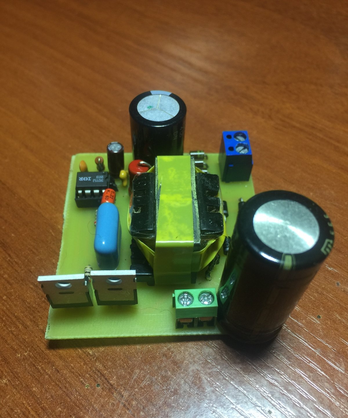
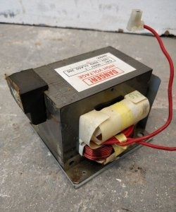
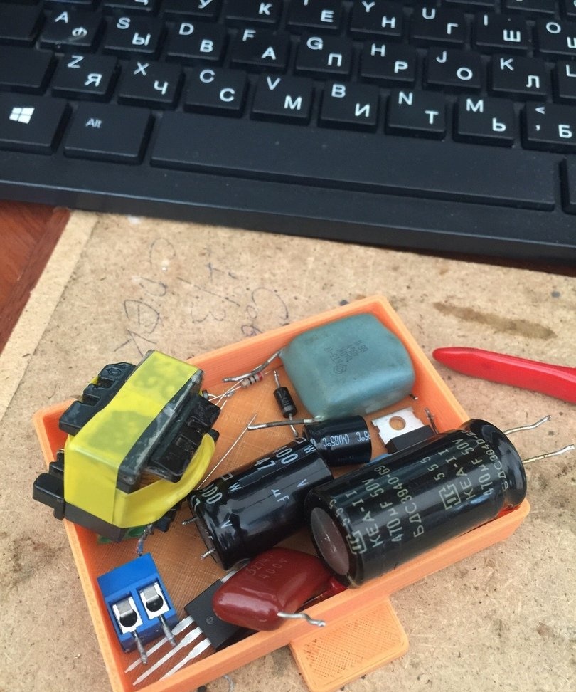
Let us return to the transformer, it can be found on the boards of computer power supplies, it is not difficult to determine here it is visible in the photo the biggest one we need it. To rewind such a transformer, it is necessary to loosen the glue with which the ferrite halves are glued, for this we take a soldering iron or a soldering hair dryer and slowly warm up the transformer, we can lower it in boiling water for several minutes and carefully disconnect the core halves. We wind all the basic windings, we will wind our own. Based on the calculation that I need to get a voltage in the region of 12-14 volts, the primary winding of the transformer contains 47 turns of 0.6 mm wire in two cores, we make insulation between the winding with ordinary tape, the secondary winding contains 4 turns of the same wire of 7 cores . It is IMPORTANT to wind in one direction, insulate each layer with tape, marking the beginning and end of the windings, otherwise it will not work, and if it does, then the unit will not be able to give all the power.

Block check


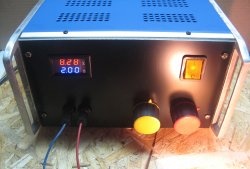
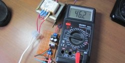
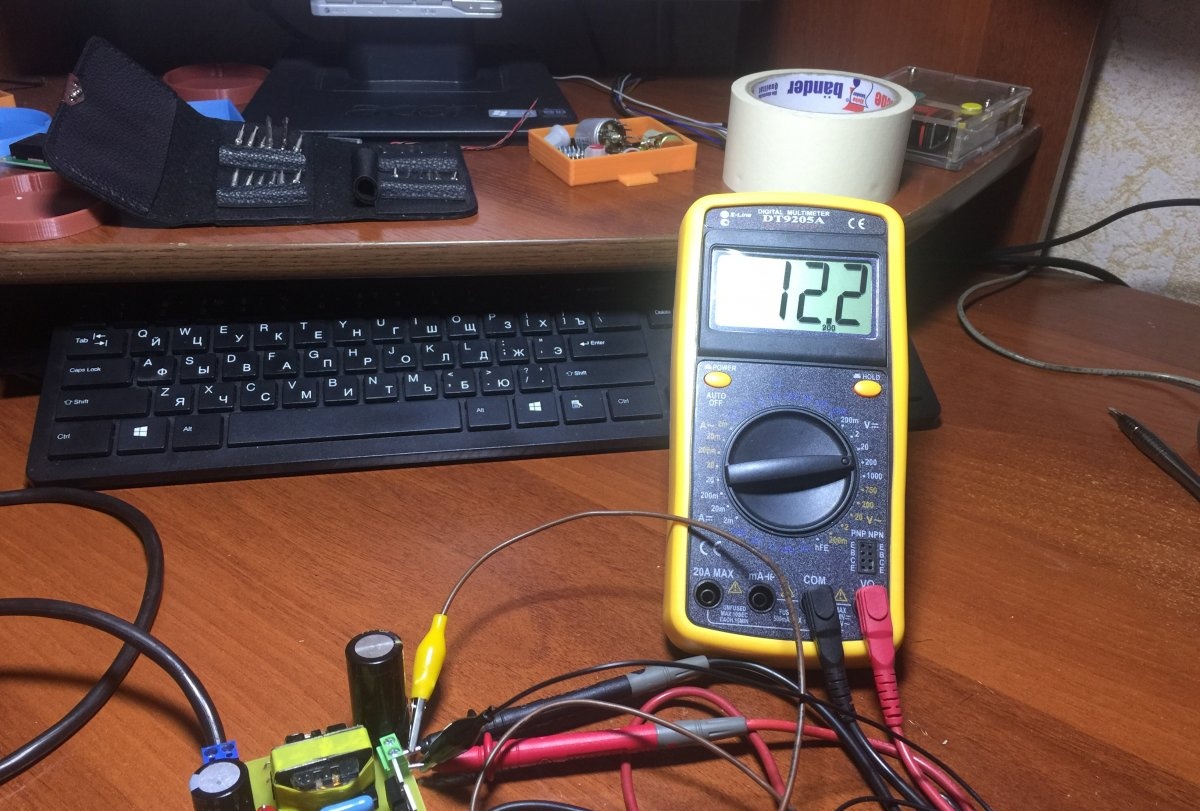
Well, now let's test our power supply, since my version is fully functional, I immediately plug it into the network without a safety lamp.
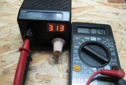
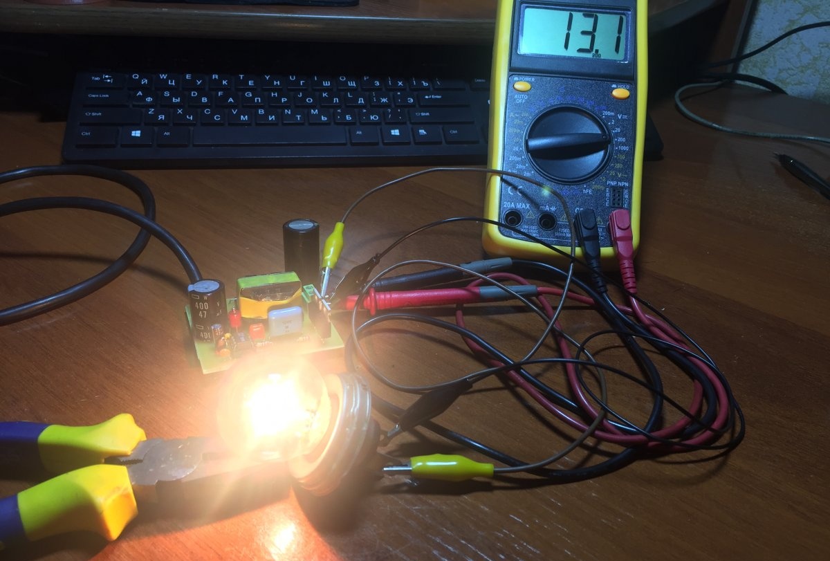
We will check the output voltage, as we see it in the region of 12 - 13 V, it does not walk much from voltage drops in the network.
DIY Powerful 12 Volt Switching Power Supply

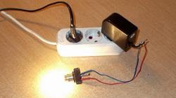
As a load, a 12-volt automobile lamp with a power of 50 watts current flows accordingly 4 A. If you add such a unit by adjusting the current and voltage, put an input electrolyte of a larger capacity, then you can safely assemble a car charger and a laboratory power supply.
DIY Powerful 12 Volt Switching Power Supply

Before starting the power supply, it is necessary to check the entire installation and turn on the mains through a 100 W incandescent safety lamp, if the lamp is on full, then look for errors when installing the nozzle, the flux is not washed out or some component is not working, etc. If the lamp is assembled correctly, it should lightly flare up and go out, this tells us that the capacitor at the input is charged and there are no errors in the installation. Therefore, before installing components on a board, they must be checked even if they are new. Another important point after starting is the voltage on the microcircuit between the 1 and 4 outputs should be at least 15 V. If this is not so, you need to select the value of the resistor R2.
DIY Powerful 12 Volt Switching Power Supply

Watch the video


come back
Comments (25)
  1. nurik
    #1 nurik Guests April 27, 2019 8:37 p.m.
    2
    Maybe you need to put a choke instead of the input transformer? (L1 according to the scheme) or there will be a boom.
    1. Guest Vova
      #2 Guest Vova Guests May 1, 2019 16:50
      1
      In the video, the correct circuit, L1 input power filter.
  2. Guest Alexander
    #3 Guest Alexander Guests April 27, 2019 8:50 PM
    2
    And what is L1? An error in the circuit!
    1. Guest Vova
      #4 Guest Vova Guests May 1, 2019 04:48
      3
      there most likely the input filter L1 the author got confused and didn’t draw it correctly on the board
  3. Guest oleg
    #5 Guest oleg Guests April 27, 2019 9:02 p.m.
    3
    Circuit Error - Filter L1
  4. Mahas
    #6 Mahas Guests April 28, 2019 04:14
    2
    On the circuit diagram there is an error in connecting the inductor and the diode bridge, and so the circuit is working, though without protection from the fool.
  5. Guest Nikolay
    #7 Guest Nikolay Guests April 28, 2019 09:47
    0
    The advantage of this circuit is that this circuit is very popular of its kind and is repeated by many amateur radio enthusiasts as their first switching power supply and efficiency and, to say nothing of the size. A set of words. And what kind of trance at the entrance, which is called - the throttle?
  6. Guest Sergey
    #8 Guest Sergey Guests April 28, 2019 12:59
    0
    And how to make 15 volts?
    1. Guest Vova
      #9 Guest Vova Guests May 1, 2019 04:29
      0
      add turns in the secondary
    2. Guest Vova
      #10 Guest Vova Guests May 1, 2019 04:37
      1
      But a circuit with an L1 error is at least superfluous, but the board must be watched
  7. Guest Andrey
    #11 Guest Andrey Guests April 28, 2019 14:27
    1
    NTC-thermistor must be installed sequentially up to the diodes, without it there will be a puff-big and the network filter is also mandatory. There is a diagram on the circuit, but not on the board. -1 to the author for the performance.
  8. Guest Andrey
    #12 Guest Andrey Guests April 28, 2019 14:28
    0
    And be sure to throttle the output after the trance.
  9. Shahismail Khalikov
    #13 Shahismail Khalikov Guests April 28, 2019 19:09
    2
    Nobody collected it, and will not collect it, moreover, it will never work. The first time you turn it on, it will either explode, and someone will be lucky and knock out traffic jams. There are a lot of mistakes. Look at least the inclusion of L1. Nurik L1 is not a transformer, but a power filter, which is included in the circuit by a 5th grade student.
    1. Guest Vova
      #14 Guest Vova Guests May 1, 2019 4:46 p.m.
      0
      And besides the confused L1 connection (it is not on the board), what other errors are there?
  10. Guest Valery
    #15 Guest Valery Guests April 28, 2019 11:18 p.m.
    0
    In general ... In the article, the scheme is not the same .... At the input of the "type", the trans is standing and not the throttle ...)))))))))))))
  11. Guest Victor
    #16 Guest Victor Guests April 29, 2019 06:12
    3
    Such an impression from the article that the "author" set the task not to help beginner radio amateurs to master the basics of circuitry, but rather to discourage their desire to experiment in the future. Apparently, this pearl is more designed for the reaction of understanding people, whose indignation will at least allow them to “earn extra money” on negative comments.
  12. Getshket
    #17 Getshket Guests April 29, 2019 10:02
    0
    In the error circuit. PCB tracing is poor.
  13. ERER
    #18 ERER Guests April 29, 2019 11:34
    0
    Why L1? Why service printed conductors? Sorry if I'm wrong.
  14. Edward
    #19 Edward Guests April 29, 2019 1:24 PM
    3
    The scheme is quite working. The author warned what he was doing for the first time.
  15. Guest Leonid
    #20 Guest Leonid Guests May 3, 2019 10:50 AM
    0
    L1 is not correctly included in the circuit; a gross error and resistance to control of field workers is overestimated; in short, the block is not reliable
  16. the guest
    #21 the guest Guests May 4, 2019 17:27
    1
    How powerful is he? Which laboratory? The author is teaching the part.
  17. Vadyukha
    #22 Vadyukha Guests May 7, 2019 20:53
    2
    Turn L1 90 degrees so that the windings are not short at the entrance, someone made a hike. Bp is simple, the main thing is that the mikruhi are alive and the field workers are not very killed. I myself collect on irk bp. R1 will burn off under a long-term load (I don’t know what the hell, but it’s warming up very much, I put 2 resistors of 10 watts per 100 kOhm in parallel). Recently I made a tie for the uzmch on tda7294 bp on this miracle, I don’t need a stabilized source there (bipolar + -32V power supply and 12 V winding were sawn on a ferrite ring, 1 kW ring power was calculated, but the 300-watt windings came out with copecks). With a 60-watt light at the input, everything is ok, blinked and started. However, when turned on without a bulb, the current-limiting 5W 3.3ohm burned out and the field workers died (ntc stands for a smooth type of start-up, but it does not save). If something powerful to collect, then only connect the load after starting bp.From the photo I see that the radiator is huge, worth the xD, he basically didn’t fall there for a hundred years, the field workers are cold, for myself I screw a small piece of iron through the gasket and grabs it by the eyes. Moreover, the trans is seemingly weak; there is no such current on the primary.
    1. Guest Vova
      #23 Guest Vova Guests May 11, 2019 15:13
      0
      It is better to feed mikruhu not from the R1 network (it starts from it) for a long time, but from an additional simple winding with a rectifier or from the output if you do not untie the input and output, then the resistor can be generally weak and more resistance.
  18. pavel urdenko
    #24 pavel urdenko Guests May 24, 2019 20:58
    0
    the author decided to make fun of the absolutely wrong scheme ...
    1. Igor Tumin
      #25 Igor Tumin Visitors June 14, 2019 3:43 p.m.
      1
      I assembled the working and correct circuit and everything works without problems, only at the input the throttle is turned over 90 degrees and that's it.

Read also

Error codes for washing machines