In radio-electronic equipment, an electronic switch is part of the control elements of the device. These can be household appliances such as: TV, microwave oven, monitor, computer, amplifier, etc., as well as industrial devices, power supplies, measuring instruments, which can be easily controlled with one button without fixing the position of the contacts; this is much more convenient and simpler than use a regular toggle switch, slider or rotary switch. This switch can be used not only in any devices, it can also be used to turn on something from a distance, such as lighting, advertising sign, ventilation, etc. The circuit decoupling is built on a relay and is completely isolated from the switching circuit.
Device diagram
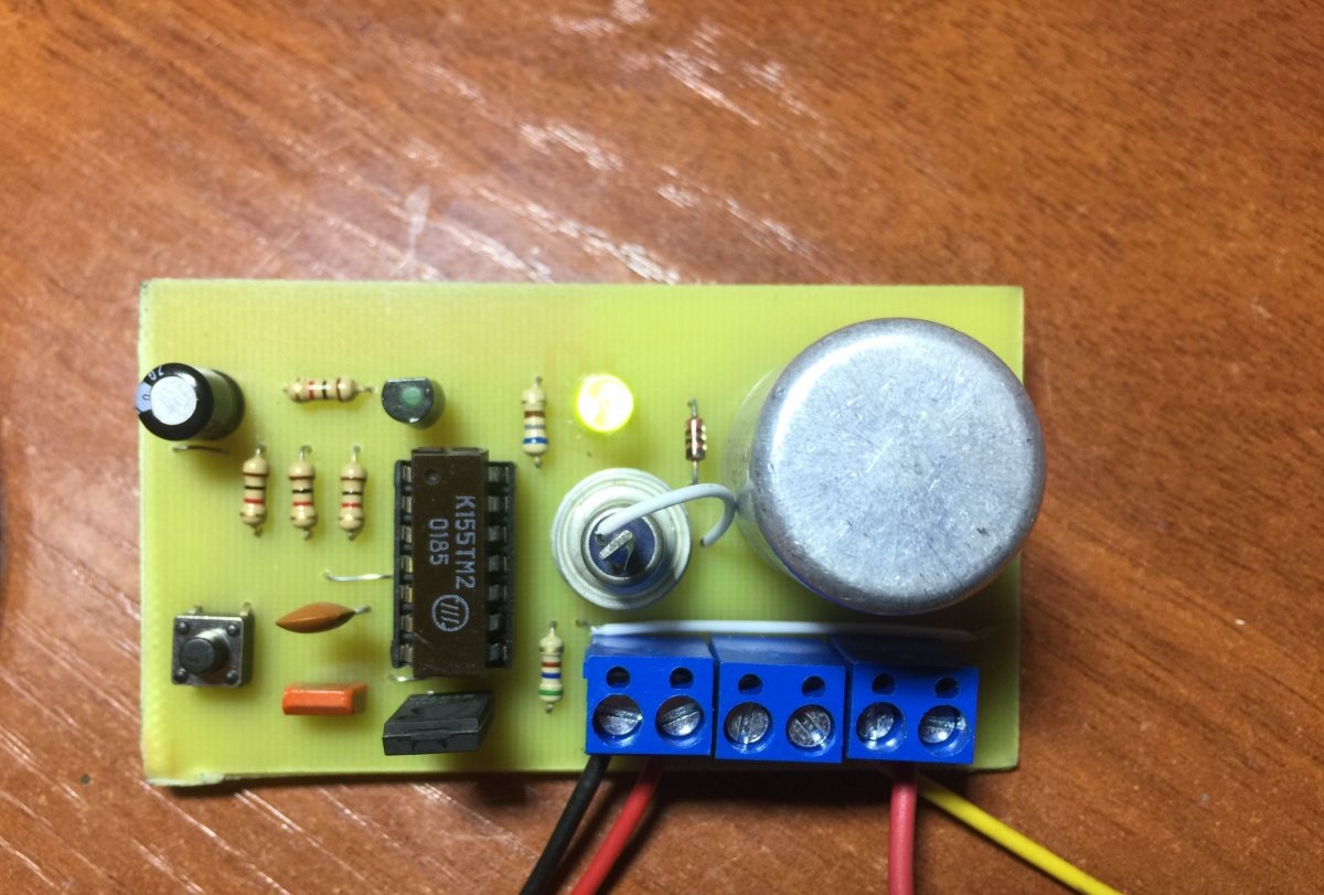
One of these options is made on the well-known K155TM2 CMOS chip.
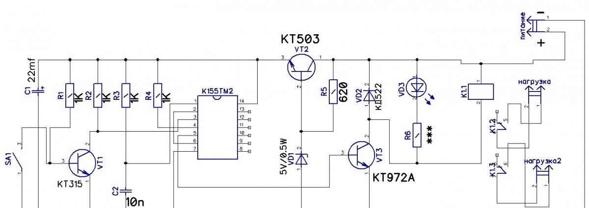
When you press the button, the 5-9-12 volt power is turned on and off, depending on what coil voltage the relay is set to. In my case, the RES-9 relay, produced in 1982, is capable of switching currents up to 3 amperes; if desired, it can be installed at higher currents of 5-6-10-12 amperes, etc.The wiring of the VT3 transistor circuit includes a relay winding, which with its contacts switches the load corresponding to the parameters of this relay. Capacitor C1 serves to prevent false operation of the contacts, and Light-emitting diode needed so that you can visually monitor the operation of this circuit (if the device is turned off, then Light-emitting diode does not light up, but if it is turned on, it lights up). The advantage of the circuit is that it consumes virtually no current from the power source when turned off.
The entire circuit is made using domestic components, which is an important advantage among radio amateurs, and therefore will be easy to replicate for many.
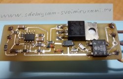
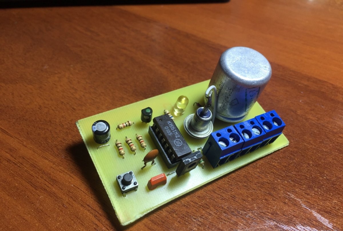
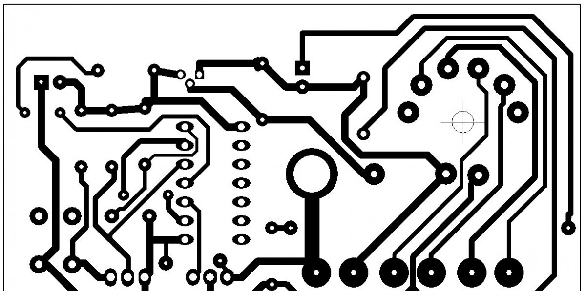
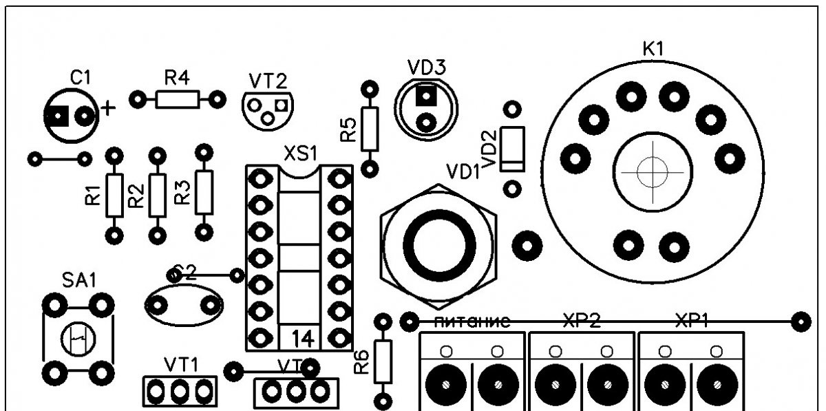
Printed circuit board
The printed circuit board was designed in the Deep Trace program. You can also redraw it using the template in the good old Sprint Layout.
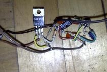
Details
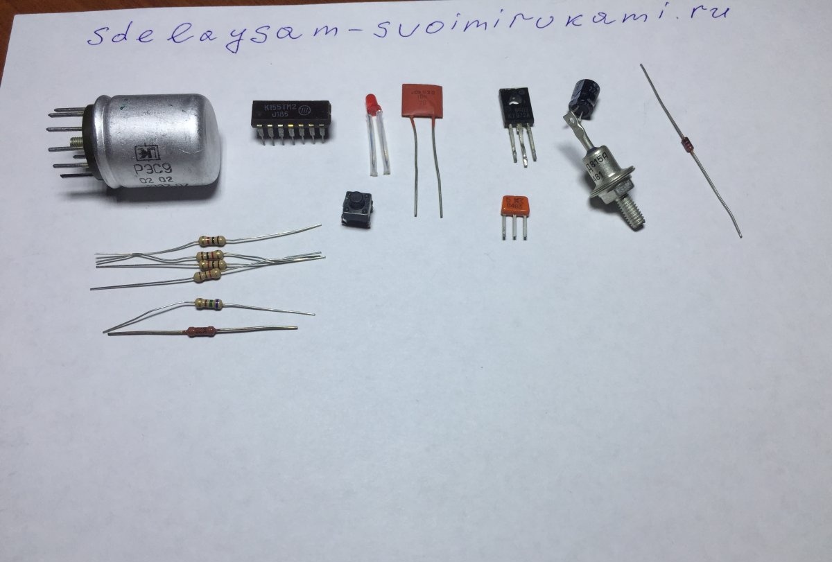
The K155TM2 microcircuit (K555 TM2 or KM155 TM2) can be replaced with a foreign analogue SN7474N or SN747J, the resistors are all low-power 0.25 W, resistor R6 is selected independently for LED depending on what supply voltage needs to be supplied to the circuit. This can be calculated in the online calculator “Calculation of a resistor for LED" Transistor KT315 can be replaced with KT3102 with any letter index or with an imported 2N2712, KT503 with 2SA1815 BC639, KT972 with BD875 or BD877, any VD1 zener diode for a stabilization voltage of 5 volts with a power of 0.5 watts (in my case it’s a Soviet D815a), diode VD2 can be replaced with imported 1N4148, any button without fixing the position of the contacts.
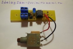
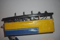
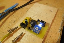
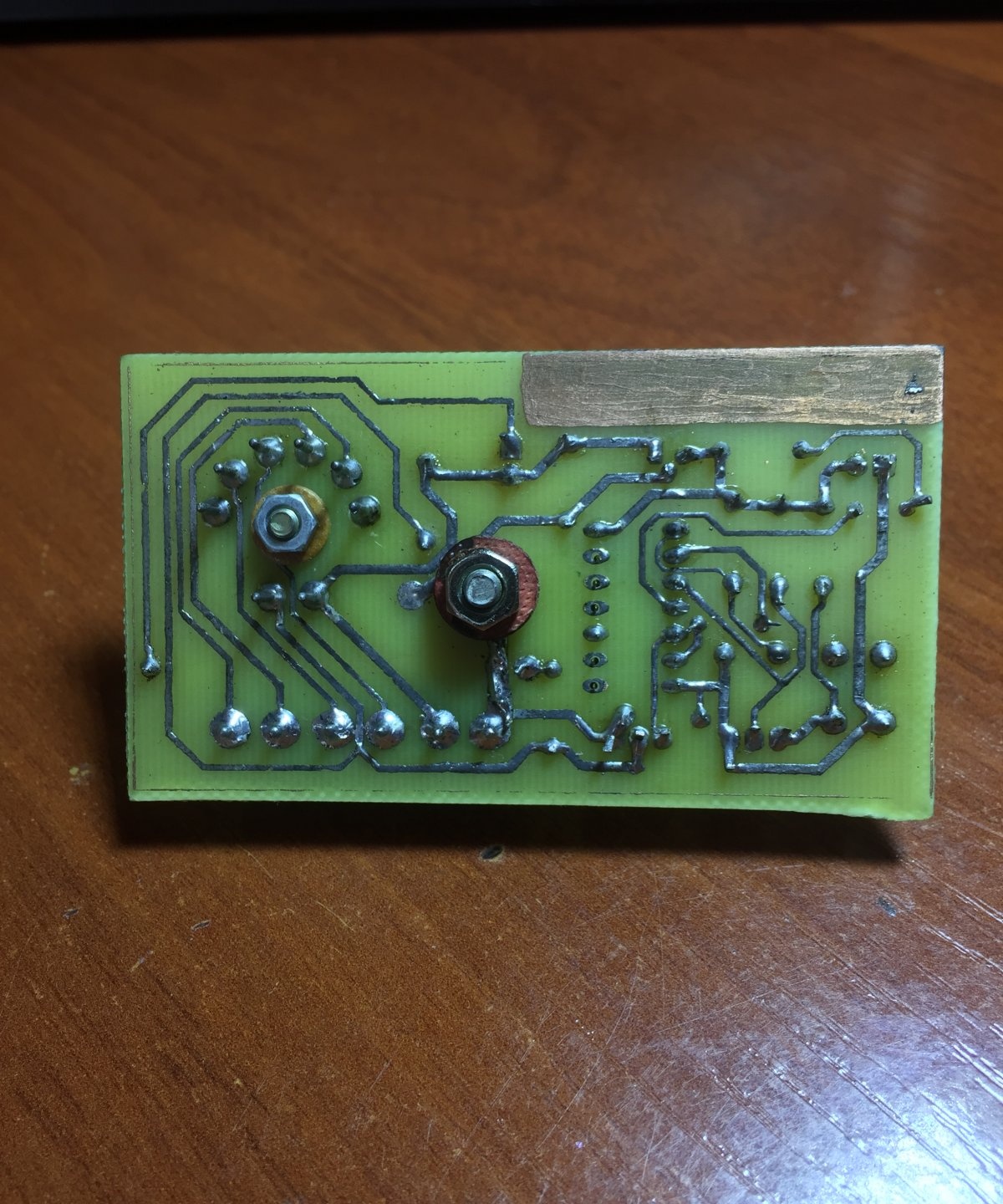
Ready device.
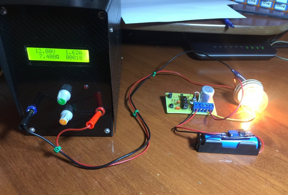
Test in action
The entire circuit is powered by 5 Volts, using a lithium-ion battery with a converter.The load circuit is connected in series with a power supply with an incandescent lamp.
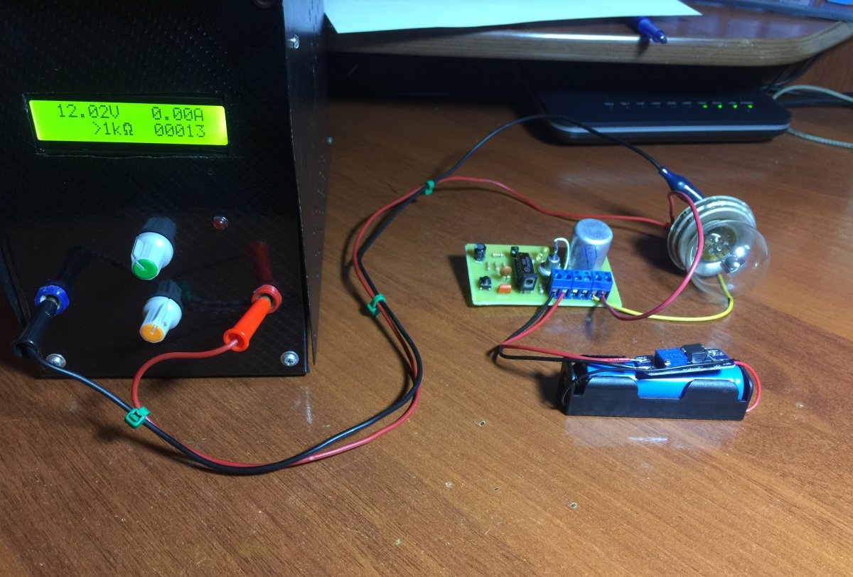
When you press the button once without holding it down, the lamp lights up and remains in this state until the button is pressed again.
Also Light-emitting diode on the board indicates the state of the circuit: enabled or disabled.
Watch the video
More details about this design can be seen in the video below.