Do it yourself
Life hacks, master classes, useful tips, recipes.
home » Electronics » DIY electronics » How to power a cooler for cooling an LED matrix at 220 V
The phyto LED matrix for illuminating plants, having its own power driver, is connected directly to the 220 V network. It works for almost half a day every day, while its body gets very hot. The matrix, attached to an aluminum radiator, receives the necessary cooling from the computer cooler. Constant 12 V for it is obtained from a network adapter, which is not always at hand.
How to power a cooler for cooling an LED matrix at 220 V

A power supply without a mains transformer is easy to make with your own hands. You will need some radio components and a soldering iron.

Description of the block operation


The transformer circuit is bulky and heavy. To lower the voltage, use the property of a capacitor to provide reactance to alternating current. If you use a divider with active resistance, problems arise:
1. With large resistor values, the circuit current is small, and the potential difference at the output is insufficient to power the device.
2. Reducing the resistance will increase the voltage, but the current through the quenching resistor will increase, it will heat up intensely until it burns out or starts a fire.
On a capacitor, alternating current and voltage are shifted in phase. At the beginning of the charge cycle, the current is large, and the voltage across the capacitor is small and gradually increases. When the capacitance is charged, the voltage increases and the current drops to zero. At the same time they are not big. The capacitor releases little power and the housing heats up little.
How to power a cooler for cooling an LED matrix at 220 V

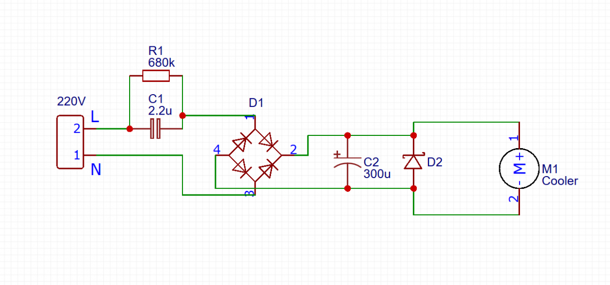
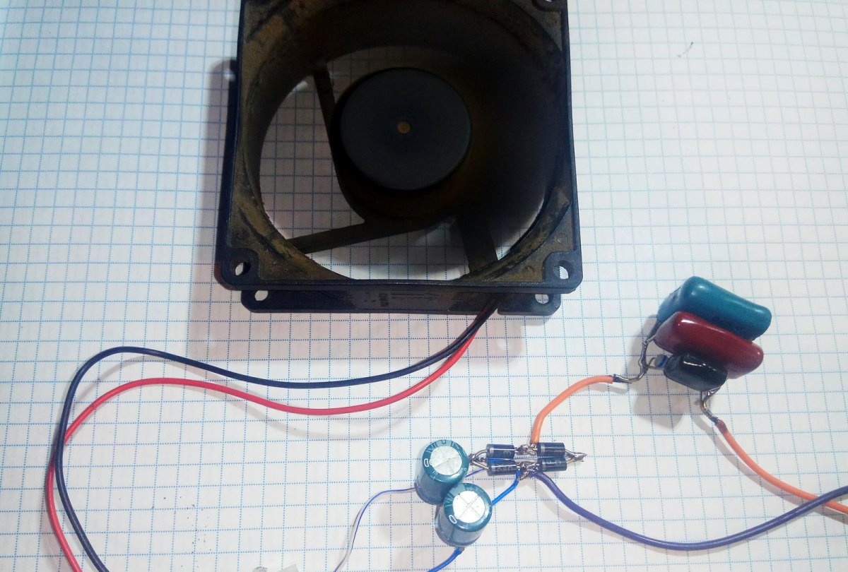
The mains voltage is supplied to the diode bridge through a capacitor. A divider is formed from the reactance of the capacitor and diodes. A small part of the voltage rectified by the bridge is smoothed by an electrolytic capacitor. The 12 V power supply normalized by the zener diode is supplied to the electric motor. A resistor is connected in parallel to the ballast capacitor, smoothing out the current surge when power is applied and ensuring the discharge of the capacitor when turned off.

Details


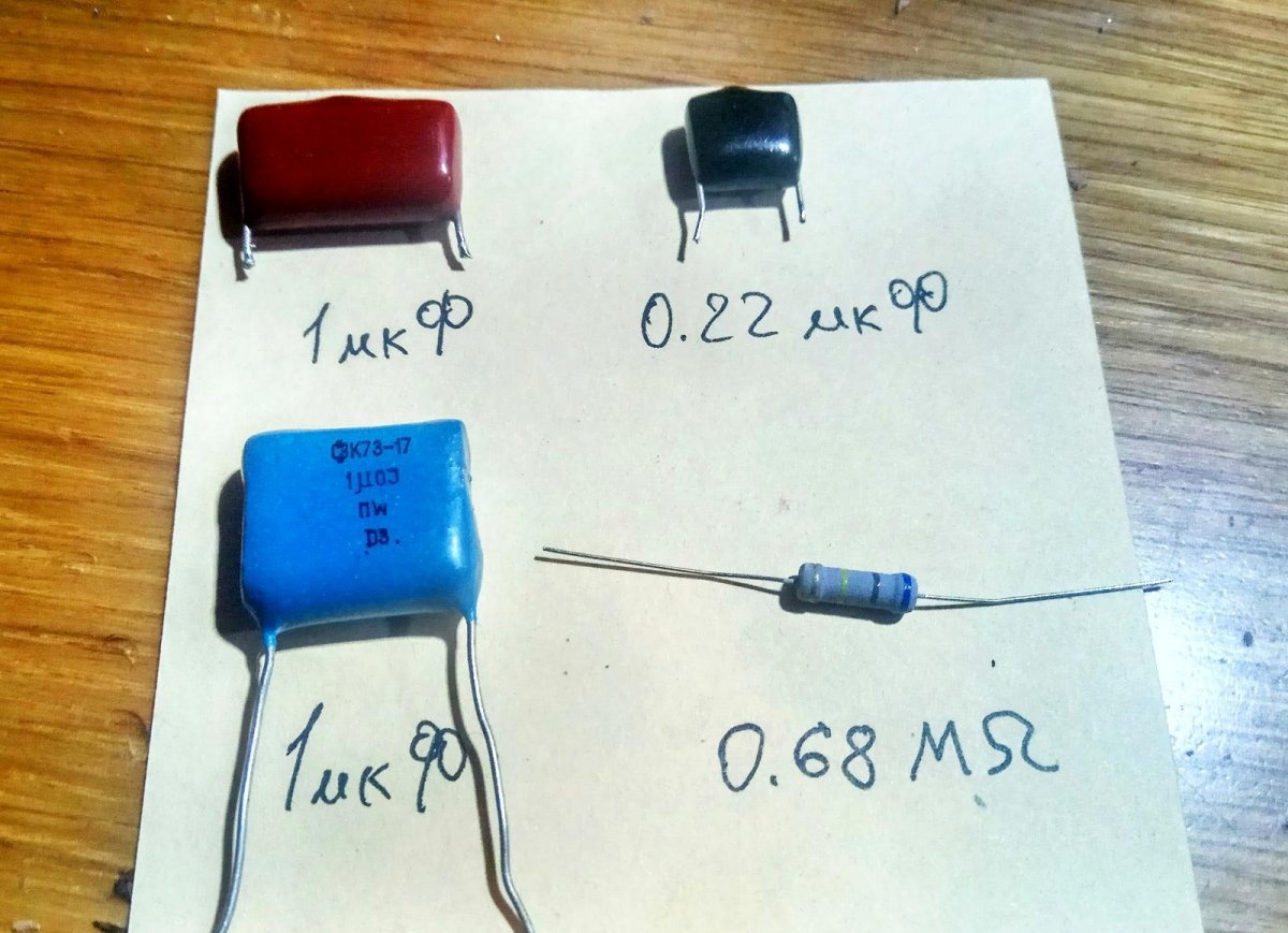
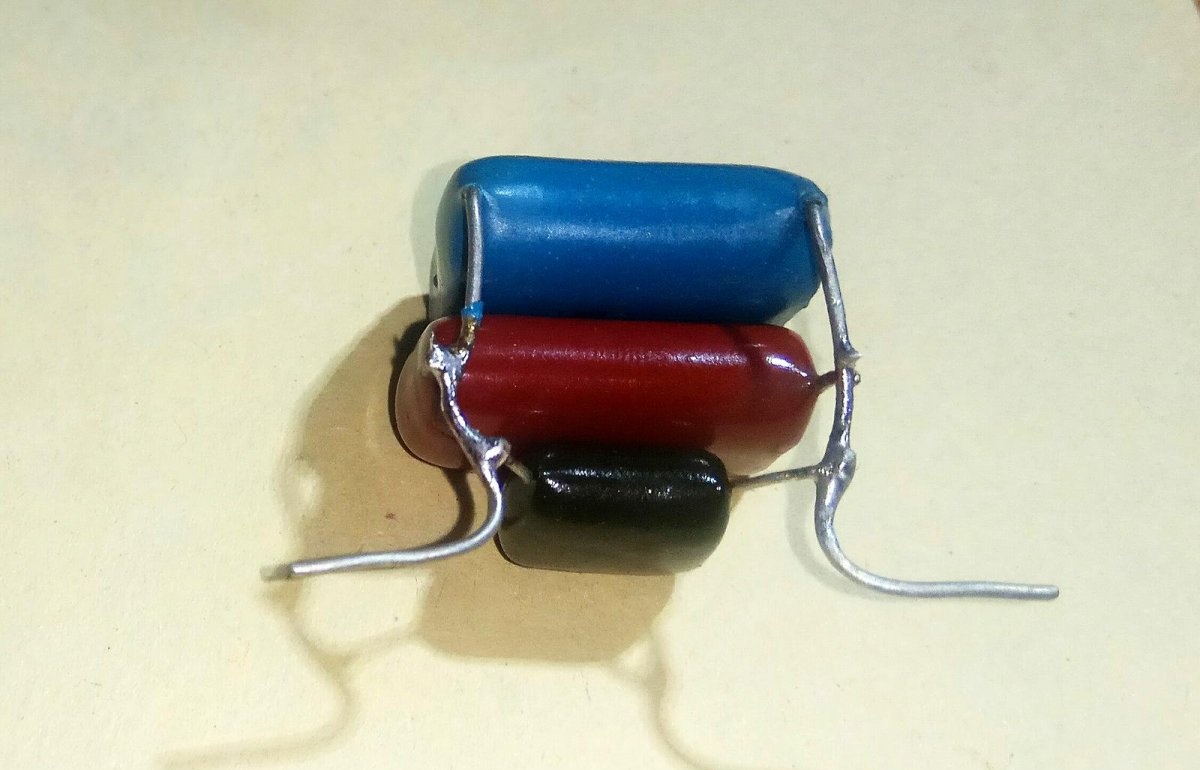
The circuit operates under a mains voltage of 220 V, so capacitors with an operating voltage of at least 600 V, paper type KGB or film K73-17, are used. The thermal dissipation power of the resistor is 0.25÷0.5 W.
How to power a cooler for cooling an LED matrix at 220 V

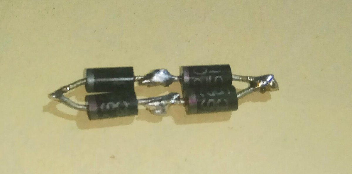
The minimum permissible reverse voltage of diodes is 400 V. D226B, KD105B-G or their imported analogues are suitable. The diodes are replaced by a bridge assembly KTs402-407. The zener diode is selected with a maximum current at an operating voltage of 12 V.
How to power a cooler for cooling an LED matrix at 220 V

Parallel connection of capacitors increases the total capacitance, summing up the ratings of all elements. The desired value is selected by combining several elements.
How to power a cooler for cooling an LED matrix at 220 V

Installation


There are few details, but their conclusions are harsh. It is possible to assemble a power supply by surface mounting without a printed circuit board, without short-circuiting the connections of the parts' pins.
How to power a cooler for cooling an LED matrix at 220 V

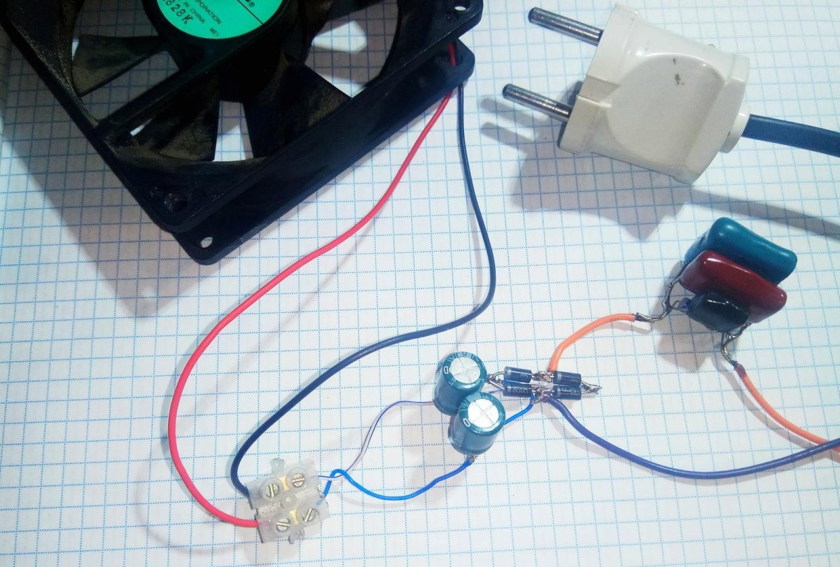
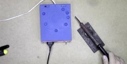
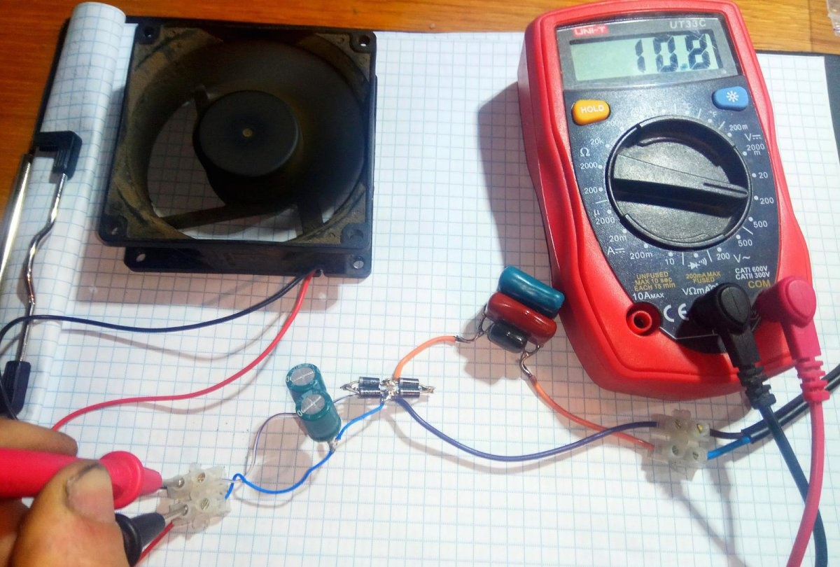
The circuit, assembled without installation errors from serviceable parts, starts the cooler engine when the power is turned on.
How to power a cooler for cooling an LED matrix at 220 V

It will help to check the operating parameters multimeter in constant voltage measurement mode, connected in parallel to the cooler. The operating voltage range of the motor is within 9÷14 volts. At the upper limits, the fan noise increases noticeably. Increasing the ballast capacitance increases the output voltage. Reducing is the opposite.
How to power a cooler for cooling an LED matrix at 220 V

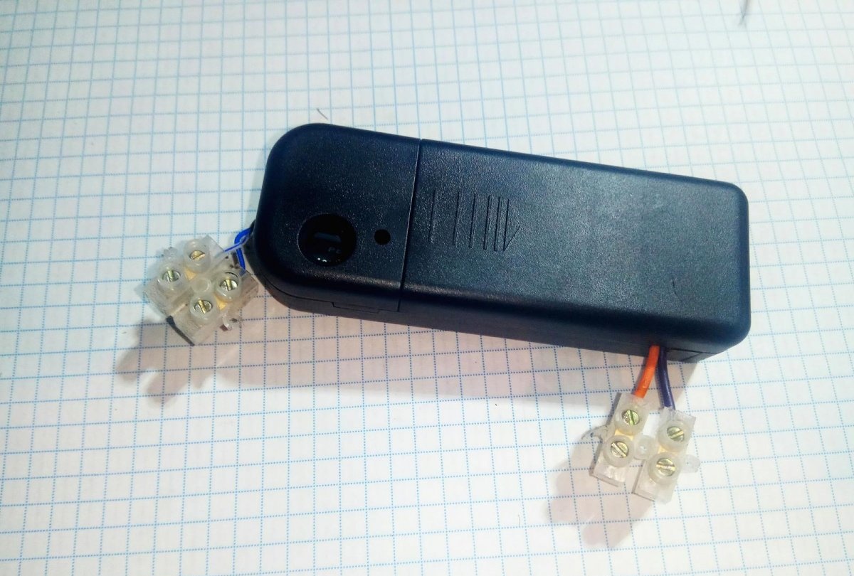
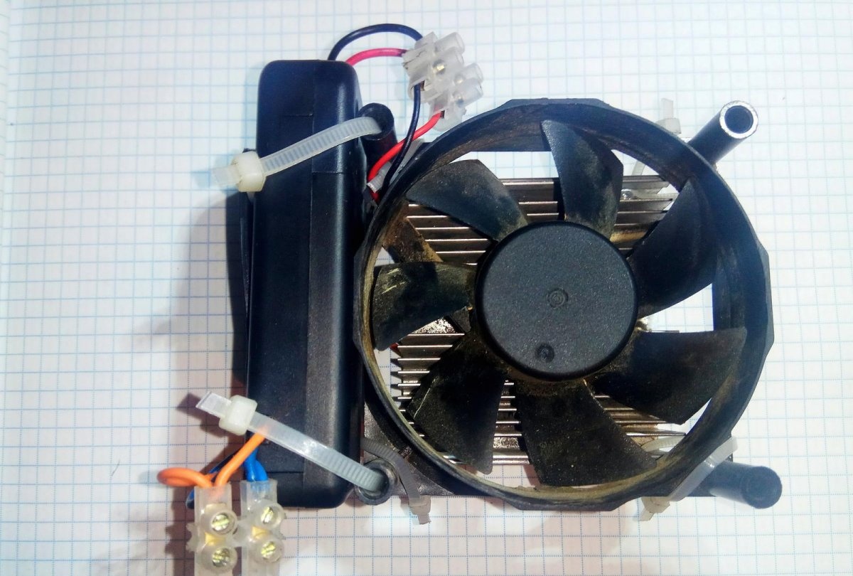
Placing the installation in a plastic case will protect against electric shock. To connect wires, terminal pairs are installed at the input and output of the block.
How to power a cooler for cooling an LED matrix at 220 V

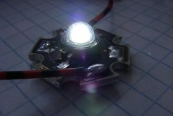
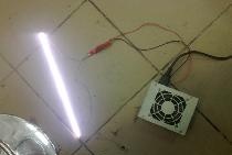
The housing is mounted on a radiator with an LED matrix placed on it. The power cord is connected to the parallel-connected power pins of the LED driver and power supply.
How to power a cooler for cooling an LED matrix at 220 V

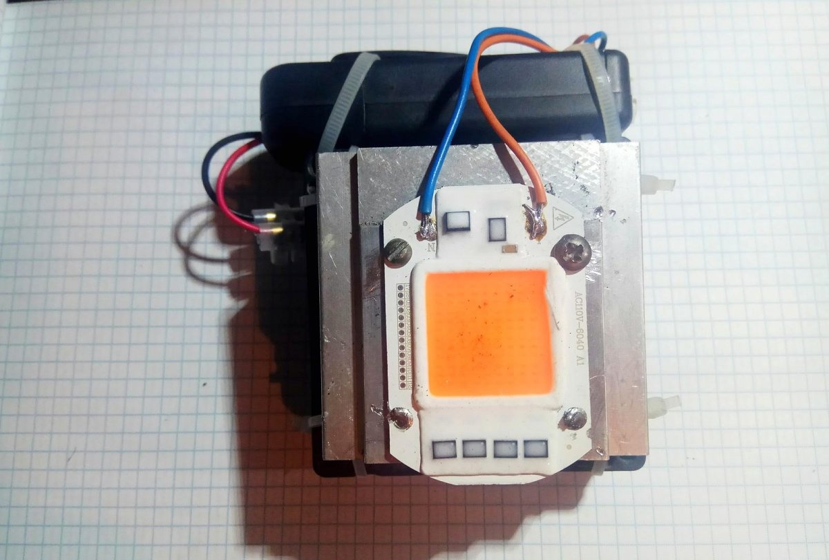
You need to make sure that nothing interferes with the free rotation of the blades.
How to power a cooler for cooling an LED matrix at 220 V

Features of the scheme


All circuit elements are under life-threatening 220 V mains voltage, therefore:
  • Perform work with the circuit with the power turned off and the ballast capacitor discharged;
  • disconnecting the load (cooler) without first turning off the power will lead to failure of the unit;
  • It is necessary to protect the circuit from short circuit by installing a fuse.

The lack of galvanic isolation of the power supply from the network is compensated by its small size, weight and low noise level during operation.
come back
Comment
  • bowtiesmilelaughingblushsmileyrelaxed relaxedsmirk
    heart_eyeskissing_heartkissing_closed_eyesflushedrelievedsatisfiedgrin
    winkstuck_out_tongue_winking_eyestuck_out_tongue_closed_eyesgrinningkissingstuck_out_tonguesleeping
    worriedfrowninganguishedopen_mouthgrimacingconfusedhushed
    expressionlessunamusedsweat_smilesweatdisappointed_relievedwearypassive
    disappointedconfoundedfearfulcold_sweatperseverecrysob
    joyastonishedscreamtired_faceangryragetriumph
    sleepyyummasksunglassesdizzy_faceimpsmiling_imp
    neutral_faceno_mouthinnocent
5+two=
Comments (7)
  1. Guest Mikhail
    #1 Guest Mikhail Guests March 29, 2019 02:14
    2
    Um....wouldn't it be simpler to install a voltage reduction board? On Ali there are different ones, from 30 rubles. Plus it's tiny in size.
  2. Anatoly Petrovich Knyazev
    #2 Anatoly Petrovich Knyazev Guests April 13, 2019 00:46
    1
    I somehow didn’t understand the author of this publication! Why show photos of parts being soldered together if the soldering is absolutely wrong? There is no resistance in the ballast, after it it is connected to the rectifier bridge, but the load is connected not after the bridge, but immediately after the capacitors! The zener diode is also missing! Not very understanding craftsmen, if they connect it this way, they may suffer from exploding electrolytic capacitors, etc., etc.
  3. Vita
    #3 Vita Guests 14 April 2019 05:08
    0
    I’ll ask again about TB. In such cases, you need a low-noise one, like humidifiers, you won’t sleep with that. The author should not be lazy and hide everything.
  4. Vita
    #4 Vita Guests 14 April 2019 05:32
    0
    Regarding the circuit, the author himself understands that it is dangerous, maybe select a power supply from an old device according to the power, in the circuit the main load is the capacitor at the input, but if it breaks there will be problems, maybe the fuse will not help if it is not selected correctly, for To protect the cooler, you can put a diode in series; perhaps it will burn out first.
  5. I
    #5 I Guests 17 April 2019 12:52
    0
    This is exactly what you should not do!!! Everything here is wrong, and I’m too lazy to comment.
  6. ozi
    #6 ozi Guests 17 April 2019 15:44
    0
    The text is fucked up. I do not recommend reading or delving into it for dummies.It’s as if the text was copied from memory from a “young technician” of the 70s, and the photos are new. The stabilizer is mentioned, but not specifically described. A narrow and not very necessary place. The circuit would need 2 diodes, 1 resistor (preferably 2) and 1 capacitor as for a classic charger. It looks like they were almost soldered like this in reality - the 2 right diodes can be safely unsoldered. Still, a larger passive radiator is better.
  7. Guest Palych
    #7 Guest Palych Guests 22 August 2021 16:52
    0
    The diode bridge is especially killing: I was the only one who noticed or someone else - even my 12-year-old Kinder will not connect the diode bridge. Well, as for the zener diode... the currents here are not weak, relatively, of course, according to the simplest estimates, with a 220V power supply, up to 150 mA of current will flow through the zener diode. Which zener diode has such stabilization currents? That's right - imported, so-called. zenner diodes, which still need to be looked for. There is only one way out available and maybe even free - instead of ZENNER, install a simple assembly of a low-current zener diode, a transistor up to 400V and one or two resistances, i.e. powerful functionally similar zener diode. Well, or assemble a chain of 15-17 pieces of 1N400X diodes assembled in series. Using this scheme (2 diodes instead of a zener diode) I made a couple of power supplies for a wall clock, in which I was already tired of changing the batteries. It’s normal, some of them have been “ticking” for 3 years without problems, the only thing is that starting is difficult - the power supply produces 1.4 volts, which is not enough for “non-ticking” ones, you need to shake them to get them going.

9 ways to properly connect wires securely

How to smoke mackerel in an apartment on a regular stove

Tricks of a bayonet that not everyone knows about

Autumn bouquet | Do it yourself

«Do it yourself - with your own hands» - a site of interesting homemade products made from scrap materials and items at home. Step-by-step master classes with photos and descriptions, technologies, life hacks - everything a real master or just a craftsman needs for needlework. Crafts of any complexity, a large selection of directions and ideas for creativity.

We recommend reading

Washing machine error codes