Do it yourself
Life hacks, master classes, useful tips, recipes.
home » Electronics » DIY amplifier » Amplifier on germanium transistors

As you know, the first transistors that replaced radio tubes were germanium. Their invention played a big role in the development of electronics, making electronic devices more functional, economical and small-sized. However, the era of germanium transistors did not last long - they were soon replaced by more advanced silicon ones. Despite this, a huge number of germanium transistors were produced, and even now, half a century later, they are not very rare.

There is an opinion that the sound of an amplifier built entirely on germanium transistors has a special color, close to a “warm tube” sound. This is what makes germanium transistors so popular among radio amateurs recently. You can listen to the sound of such an amplifier with your own ears if you assemble a very simple circuit given below.

Amplifier circuit

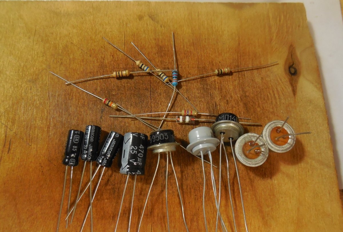
The circuit consists of 5 germanium transistors and a small handful of other parts. Below are several transistor options for this circuit.

  • T1 – MP39, MP14, MP41, MP42 (PNP)
  • T2, T4 – P217, P213, P210, P605, GT403 (PNP)
  • T3 – MP38, MP35, MP36 (NPN)
  • T4 – MP39, MP14, MP41, MP42 (PNP)

Any other similar transistors will also be suitable, low-noise ones will be most preferable. It should be noted that the output stage (T2 and T4) must have identical transistors; it is advisable to pair them with the closest gain. Diode D1 is germanium, for example, D9, D18, D311, the quiescent current of the amplifier depends on it. All capacitors are electrolytic, for a voltage of at least 16 volts. The supply voltage of the circuit is 9-12 volts.

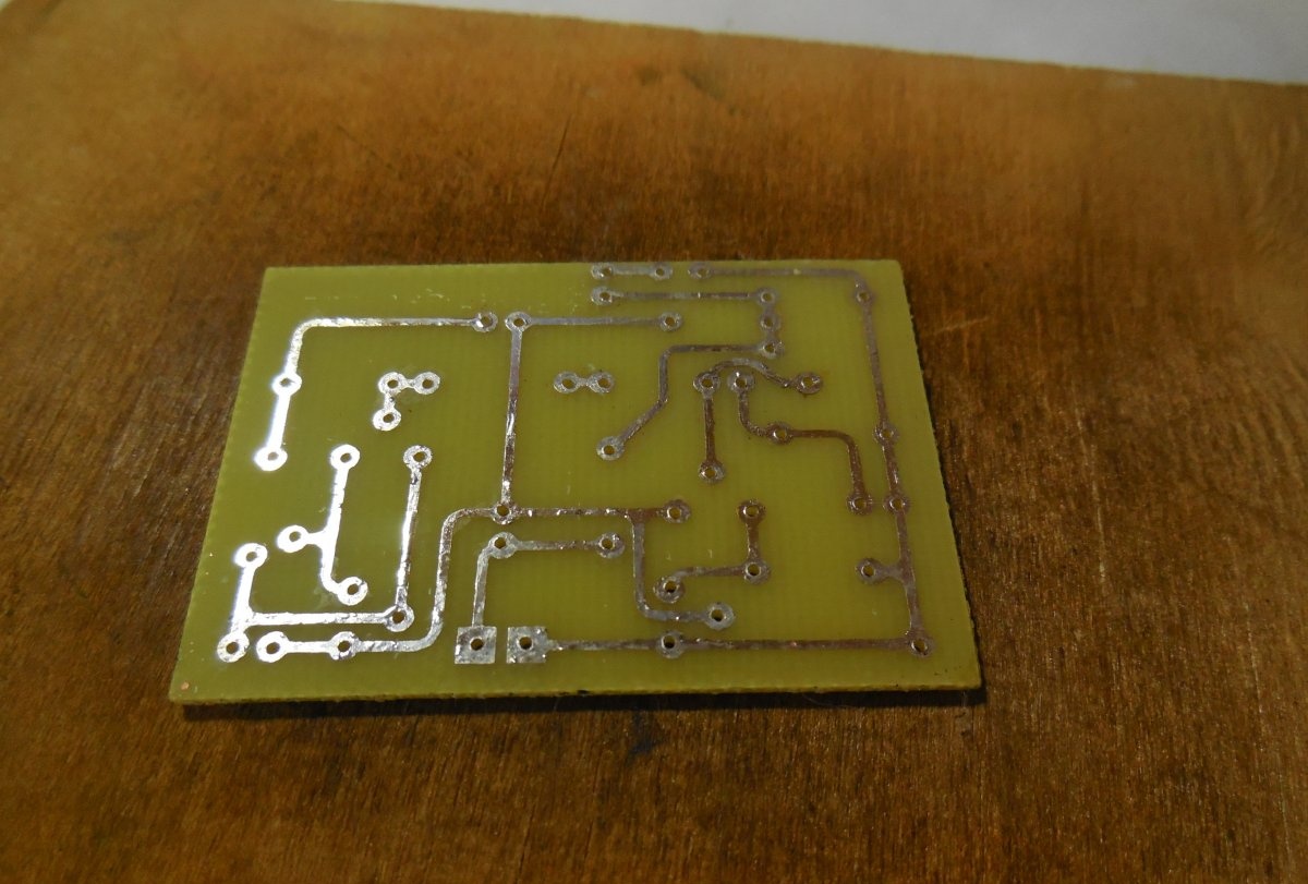
Printed circuit board:
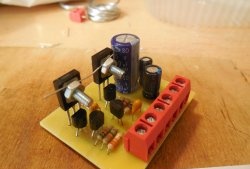
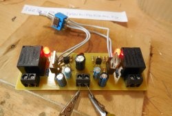
usilitel-na-germanievyh-tranzistorah.zip [12.92 Kb] (downloads: 1842)

Amplifier assembly

The circuit is assembled on a board measuring 40x50 mm, which can be made using the LUT method. Below are photos of the finished tinned board.

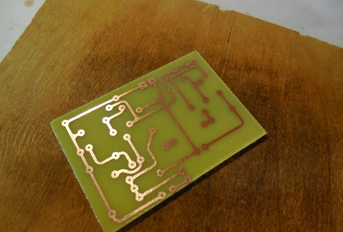
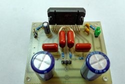
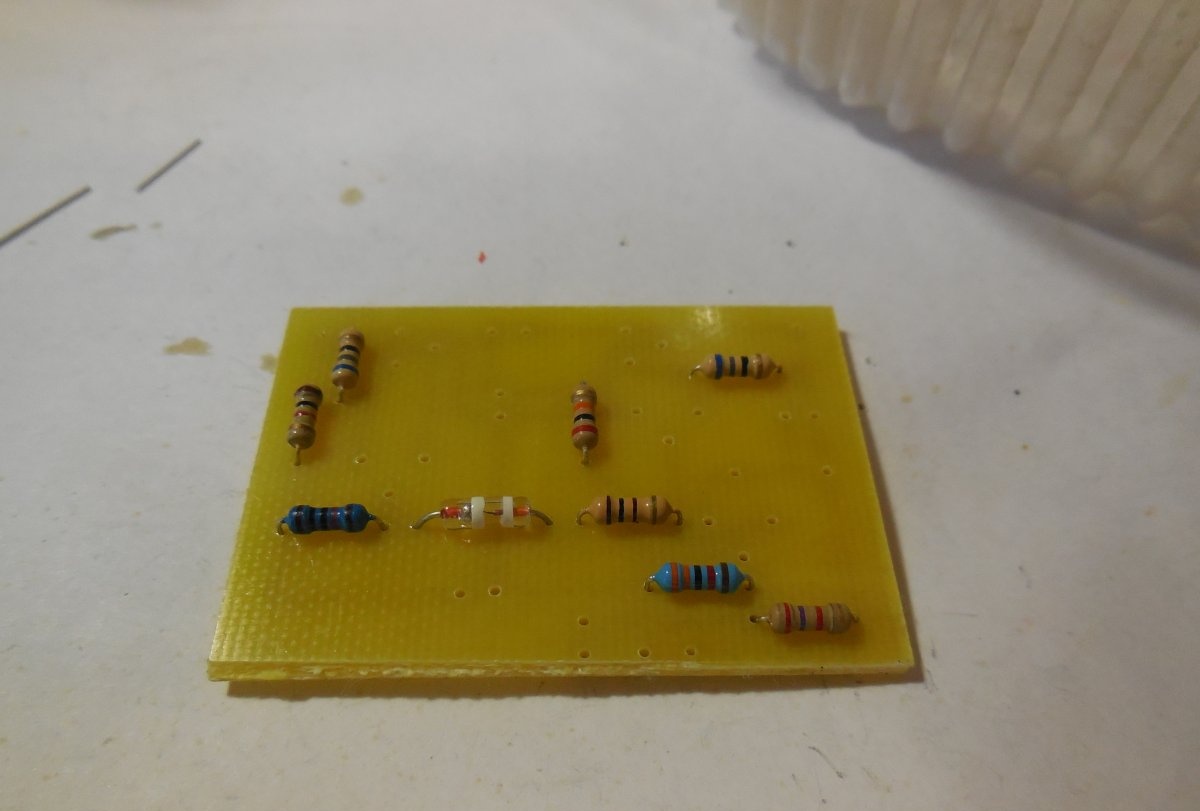
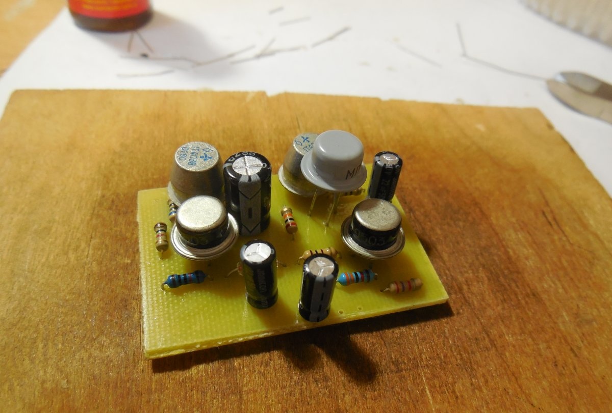
Now you can start installing the parts. First of all, resistors are placed on the board, followed by larger capacitors and transistors. It should be borne in mind that germanium transistors, unlike silicon ones, are much more sensitive to overheating.

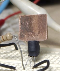
Powerful output transistors heat up during operation at high volumes, so it is advisable to install them on a radiator (if the transistor case provides such a possibility) and connect them to the board with wires.

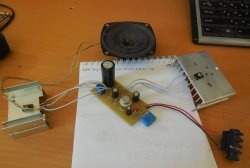
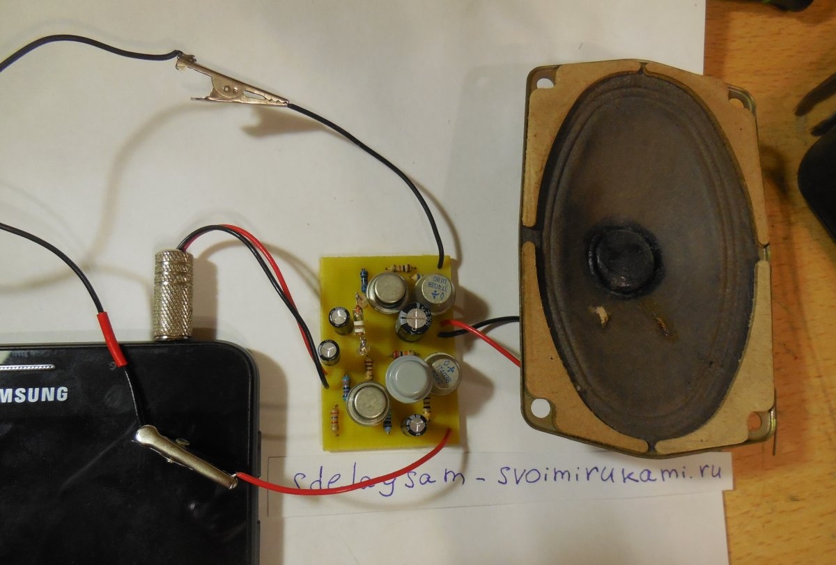
After installing all the parts on the board, all that remains is to solder the power wires, signal source and speaker output. The final stage of assembly is to wash off any remaining flux from the board, check for correct installation, and test adjacent tracks for short circuits.

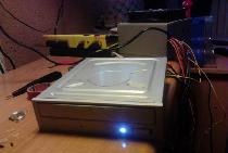
First startup and setup

The germanium amplifier requires quiescent current adjustment, which is set by diode D1. The first step is to apply voltage to the circuit by connecting an ammeter to the gap in the supply wire.If there is no signal at the input, the circuit should consume approximately 20-50 mA. The higher the quiescent current, the greater the heating of the output transistors, but this has a positive effect on the sound quality. If the quiescent current is too low, the sound becomes unintelligible, grinding and hoarseness appear. The current can be increased by adding one or more diodes in series with D1. In my case, to obtain acceptable sound quality, I had to add two additional diodes.

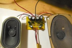
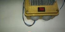
Similar amplifier circuits based on germanium transistors were widely used in antique players, tape recorders, and radios, so it will definitely appeal to all lovers of antiquity. The output power is approximately 5-10 watts with a radiator, so the amplifier is enough to sound an entire room. Happy building!

Watch the video

come back
Comment
  • bowtiesmilelaughingblushsmileyrelaxed relaxedsmirk
    heart_eyeskissing_heartkissing_closed_eyesflushedrelievedsatisfiedgrin
    winkstuck_out_tongue_winking_eyestuck_out_tongue_closed_eyesgrinningkissingstuck_out_tonguesleeping
    worriedfrowninganguishedopen_mouthgrimacingconfusedhushed
    expressionlessunamusedsweat_smilesweatdisappointed_relievedwearypassive
    disappointedconfoundedfearfulcold_sweatperseverecrysob
    joyastonishedscreamtired_faceangryragetriumph
    sleepyyummasksunglassesdizzy_faceimpsmiling_imp
    neutral_faceno_mouthinnocent
3+three=
Comments (28)
  1. Garry Hakobyan
    #1 Garry Hakobyan Guests 28 January 2019 18:35
    3
    Place a differential amplifier at the input and you will get much better distortion...
  2. Serzh
    #2 Serzh Guests 28 January 2019 23:13
    1
    Correct:
    T5 – MP39, MP14, MP41, MP42 (PNP)
  3. MiHaAd
    #3 MiHaAd Guests January 29, 2019 05:12
    1
    Be more careful in the description of T4
  4. Grig
    #4 Grig Guests January 29, 2019 09:51
    1
    T4 SHOULD BE THE SAME TYPE WITH T2!!!! These are the two power output transistors in this circuit. Correct the mistake.
  5. Alexander
    #5 Alexander Guests January 31, 2019 01:48
    3
    Stories that the sound of an amplifier with germanium transistors differs from the sound with silicon ones is amusing nonsense. Another thing is an amplifier with field-effect transistors versus an amplifier with bipolar ones. The field amplifier will have characteristics closer to those of tube amplifiers. The presented amplifier circuit will generally not be very good in terms of distortion, if only because one of the output transistors is connected to the “common emitter” connection and the second to the “common collector” circuit; the output resistances of these circuits differ by an order of magnitude, which will give additional distortion. The best option is to use complementary pairs of transistors.-)
    1. ZX
      #6 ZX Guests February 10, 2019 01:57
      9
      Well, it's not that stupid. I have owned and listened to a lot of different amplifiers, as well as built them myself. So I’ll say that very often German amplifiers sound really good. Take old Tandberg receivers and listen. And I also disagree about field-effect transistors. I had a lot of amps on Mosfets. Everyone sounds dead, Sonya and others. They were immediately outplayed by bipolar people. Polevik is not a lamp at all, as many people mistakenly imagine due to some similarity in control. Take all the expensive high end amps. They abandoned field workers there a long time ago and there are a bunch of bipolar workers in parallel. Look at companies like Mark Levinson or Plinius and Krell. You won’t see field workers there. I hope you don’t think that listeners of such technology don’t understand anything about sound?... Just like the developers.
      1. Guest Sergey
        #7 Guest Sergey Guests February 26, 2019 11:16
        3
        Rich audiophiles (listeners of such equipment) are mostly technically illiterate sectarians who believe in the special influence on the sound quality of wires at a higher price than sound amplification equipment. Therefore, I find it pointless to appeal to their choice and the solutions used by the developers of equipment aimed at this group of consumers.
        Polevik is not a lamp at all, as many people mistakenly imagine due to some similarity in control

        A field worker not operating in key mode is, in any case, much more of a “lamp” than a bunch of bipolars.
        They abandoned field workers there a long time ago and there are a bunch of bipolar workers in parallel.

        About 25 years ago, among “true audiophiles,” the use of bipolar (and there were essentially no other power transistors at that time) in the audio path was considered bad manners. Because nothing spoils the sound more than “semiconductors” and, accordingly, only “tube” sound can be of high quality.
        But for some reason, all these true connoisseurs of high-quality sound forget that over 95% of the content that they listen to on their correct “tube” sound amplifier equipment, before getting into the conductors of their expensive equipment, at best, passes in analog form to the corresponding media via a variety of semiconductor amplification elements used in mixing consoles, reverbs, limiters, exciters, equalizers and, of course, recording equipment. And even (lately) they are exposed, oh horror! analog-to-digital, and then digital-to-analog conversion in non-tube microcircuits with cutting off all harmonics, if not above 20 kHz, then in the most ideal case above 192 kHz...
        And the tube sound...what is tube sound - this is the magic of these wonderful luminous electro-vacuum devices with frequency response distortions characteristic of the amplifiers assembled on them, adding a special charm to the sound of phonograms..
        1. Guest Alexander
          #8 Guest Alexander Guests 20 March 2019 19:48
          2
          This is a new collection of money, for newly increased prices for lamps, for a beautiful nickel-plated chassis. Maybe for some it’s nostalgia. At one time I was already fed up with lamps. I am not seduced. Power consumption and the eternal search for output transformers.
        2. Sergey
          #9 Sergey Guests 10 February 2020 11:10
          1
          It has long been clear to everyone that sound is what is reproduced by the speaker and not by electrons wandering in the equipment. Therefore, tube sound is still relevant today.
        3. Guest Alexander
          #10 Guest Alexander Guests 16 November 2020 22:37
          2
          Well, listen to your Chinese - what are you doing. The digital will not spoil the sound at all if it is recorded and recorded in analog.
  6. Guest Alexey
    #11 Guest Alexey Guests 31 January 2019 12:26
    1
    Is the separating capacity at the output small?
  7. Anton
    #12 Anton Guests 31 January 2019 15:44
    2
    And finally, the sound quality depends not on the type of transistors used, but on the bandwidth of the amplification path. Although our ear can hear frequencies up to 20,000 Hz, it can perceive overtones of fundamental frequencies. At least up to the seventh harmonic of the fundamental tone.
    And tube amplifiers had a linear frequency response up to hundreds of kilohertz, and as a result - high sound quality.
    Achieve a linear characteristic of at least 150-200 kilohertz on a transistor amplifier and you will be happy.
  8. Guest Oleg
    #13 Guest Oleg Guests February 1, 2019 05:02
    0
    Everything is fine, everything is fine. How to set the quiescent current.
  9. Guest Alexey
    #14 Guest Alexey Guests February 1, 2019 08:09
    3
    For young DIYers, as soon as they do the first one, they will want something else.This is knowledge, and if something you’ve done starts to work, then it’s generally inspiring. This is not for the sake of sound quality, it is for the sake of introducing the boys to the education of humanity in them...
  10. Guest Alex
    #15 Guest Alex Guests 15 February 2019 03:40
    2
    It is, of course, complete nonsense that germanium transistors will give some kind of special sound. and the GT408 used in the circuit generally have a cutoff frequency of 8 kHz. and as has already been correctly written here, in the output stage one operates in the circuit with OK, the second with OE. in general, the scheme is suboptimal. If you debug the quiescent current, the sound will be standard, like the VEF receiver of those years.

How to make a turbo brush for a trimmer that washes everything

How to reliably restore broken threads on plastic

How to make a workshop floor from wooden blocks with your own hands

How to decorate a bathroom with PVC panels

«Do it yourself - with your own hands» - a site of interesting homemade products made from scrap materials and items at home. Step-by-step master classes with photos and descriptions, technologies, life hacks - everything a real master or just a craftsman needs for needlework. Crafts of any complexity, a large selection of directions and ideas for creativity.

We recommend reading

Washing machine error codes