KT315 is the legendary domestic transistor, copies of which are present in large numbers at each amateur radio amateur. Not surprising - after all, this is the very first mass-produced silicon transistor, you can find it in almost any Soviet device. By the beginning of the 90s, more than 7 billion pieces were manufactured. By modern standards, the KT315 is far from an ideal transistor in its parameters, because new, cheaper and more advanced semiconductor devices have been invented and have long been produced. But, nevertheless, sometimes I want to get a handful of old transistors from a distant box and collect something unpretentious on them, for example, an amplifier.
Scheme
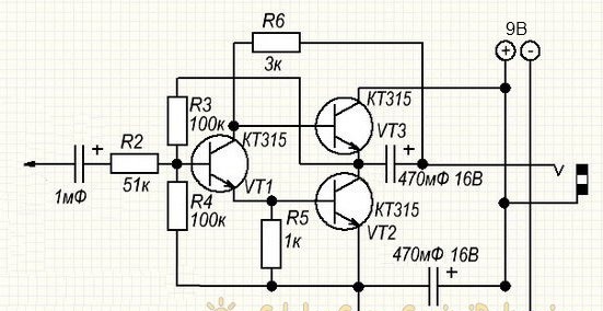
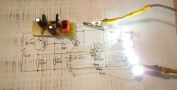
The circuit is special in that it does not contain any other active elements, except for KT315 transistors. This circuit will be an excellent choice not only for lovers of antiquity, but also for those who do not have the opportunity to get other transistors. The values of the resistors are not very critical and can vary within 20-30%, just like with capacitors. It is advisable to choose transistors for this circuit with a large gain, in this case the maximum volume of the amplifier will increase. In this case, it is necessary to observe the condition - both transistors of the output stage must have the same letter index. The circuit starts working with a voltage of 5 volts, the most optimal power supply is 9 volts. The current consumption in this case is approximately 20 mA and is almost independent of the volume level. It should also be borne in mind that to reproduce a stereo signal, the circuit must be repeated twice.
Amplifier assembly
[116.21 Kb] (downloads: 202)
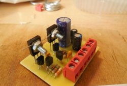
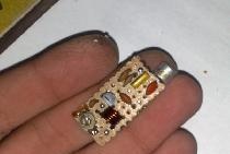
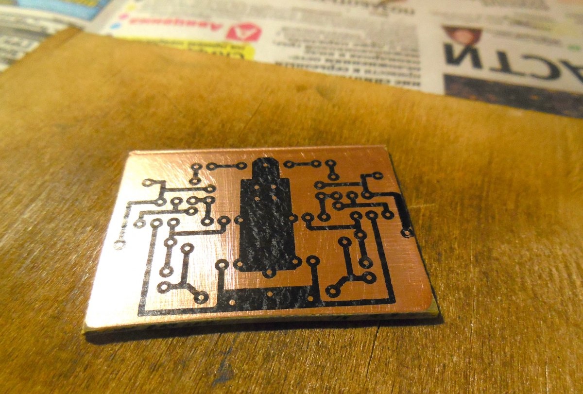
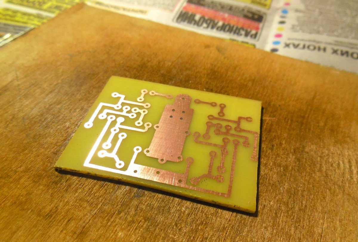
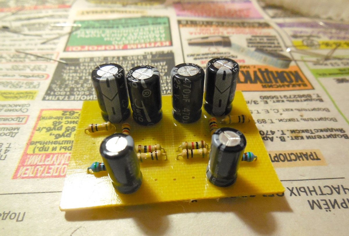
The circuit is assembled on a printed circuit board measuring 50x40 mm, which already contains both channels. First of all, using the laser-ironing technology, we manufacture the board itself. Below are some photos of the process.
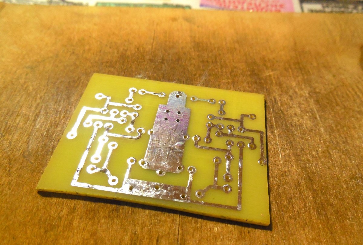
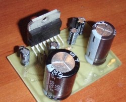
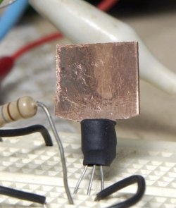
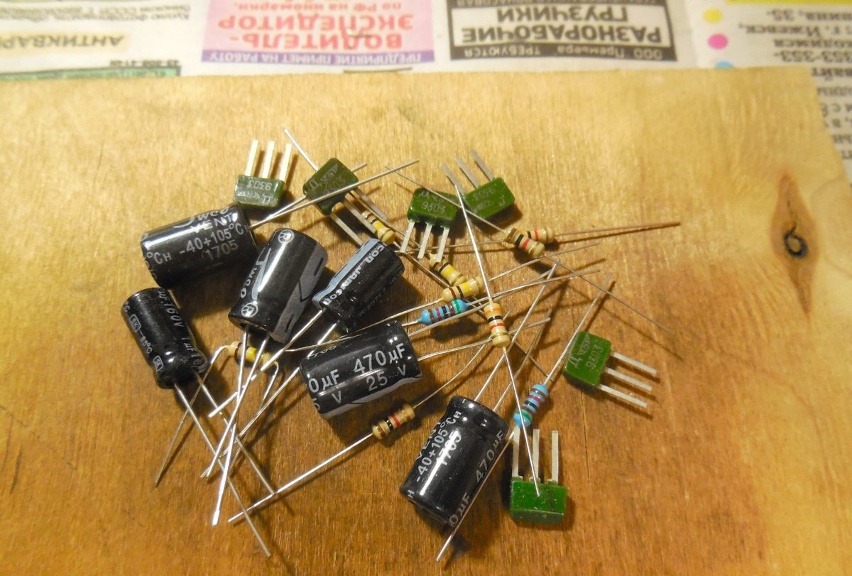
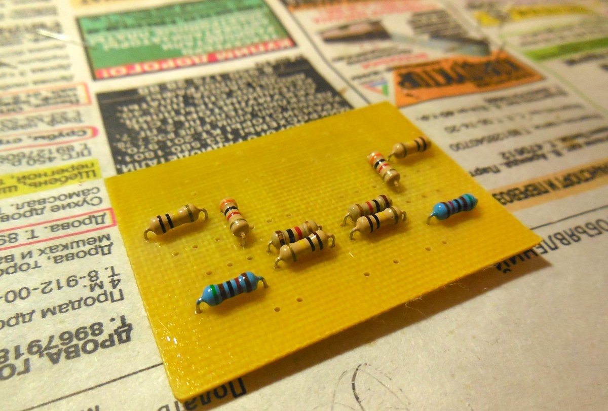
After the board is ready, you can begin to solder the parts. First of all, resistors are installed on the board, then capacitors with transistors. The terminals of the KT315 transistors, in contrast to the conclusions of modern parts, are thin flat strips that are very easy to tear off the case, so you should not put too much effort on them.
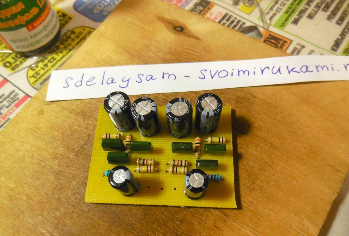
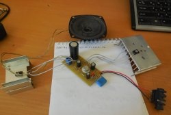
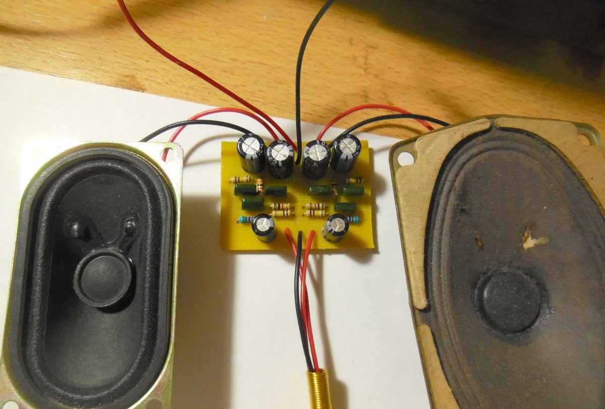
After installing the parts on the board, it is necessary to check the adjacent tracks for a short circuit, to verify the correct installation of transistors - because they can easily be soldered on the wrong side. The base terminal of the KT315 is on the right, if you look at the front side of the transistor. Now it remains only to connect the board with the speakers with the speakers, the sound source, apply power and the amplifier is ready.
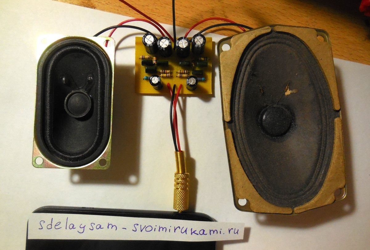
First launch and testing
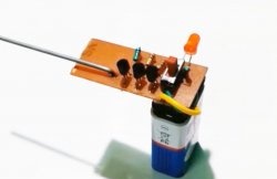
The amplifier can work with speakers with a resistance of 4-8 Ohms, and you can also connect headphones to its output that lack the power of a regular signal source. The signal source can be, for example, a telephone, player or computer. Before the first inclusion in the gap of one of the supply wires, you need to turn on the milliammeter and measure the current consumption, it should not exceed 100 mA in total for both channels. If it exceeds, then it is worth it to reduce the supply voltage. Due to its low consumption, this amplifier can be powered even from the crown.The power of the resulting amplifier is approximately 0.1 watts - a little, but quite enough for quiet listening to music indoors. Have a nice build!