DIY car amplifier remodeling
Typically, in such amplifiers, power field-effect transistors in the power supply unit (converter) or powerful transistors of the terminal stages of the power amplifier burn up, which is not difficult to replace. These transistors can be checked for operability by a conventional tester, measuring the resistance between the "legs" -taps - for the "punched" elements, these resistances will be almost zero with any combination and polarity of the measuring probes. If replacing high-power transistors does not restore the amplifier’s performance, then the reason is more “deep”, and it is quite problematic to determine the health of microcircuits and other small elements, especially in SMD-cases without soldering. In this case, it is much easier and faster to assemble a new unit, instead of the faulty one. For example, if the amplifier does not work, but its power supply-converter produces normal operating voltages, then you can remove from the board all the details related to the amplifier stages and install a new circuit assembled on its own in the vacant space on the board. In principle, it will be enough to remove the powerful transistors of the output and pre-terminal stages, and the entire low-current part (pre-amplifiers) can be left on the board. They do not take up much space and will not interfere in any way. All power paths going to this part from the converter, of course, should be found and carefully cut in order to avoid possible short circuits during the installation of additional boards.
Thus, we will only have a working power supply-converter and enough free space to accommodate a new circuit.
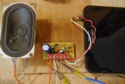
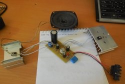
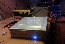
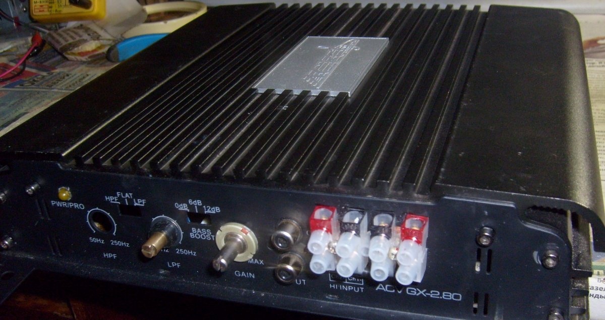
Here is an example of such a repair-conversion of a two-channel amplifier into a single-channel, for a subwoofer:
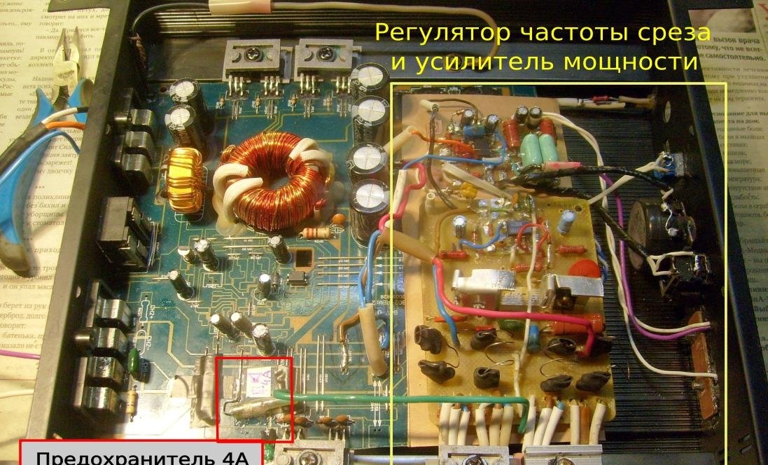
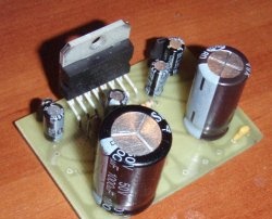
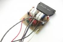
The picture shows the remaining “native” part - the voltage converter and the added home-made circuit - the adder and filter unit and the terminal power amplifier. Below are the schematic diagrams of the new, added “part”.
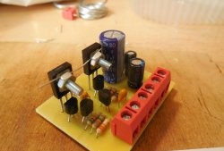
Power amplifier circuit
It is assembled according to a rather simple scheme, while ensuring quite decent characteristics. Depending on the used terminal transistors and the value of the supply voltage, such an UMZCH can produce up to 200 watts at a load of 4 Ohms:
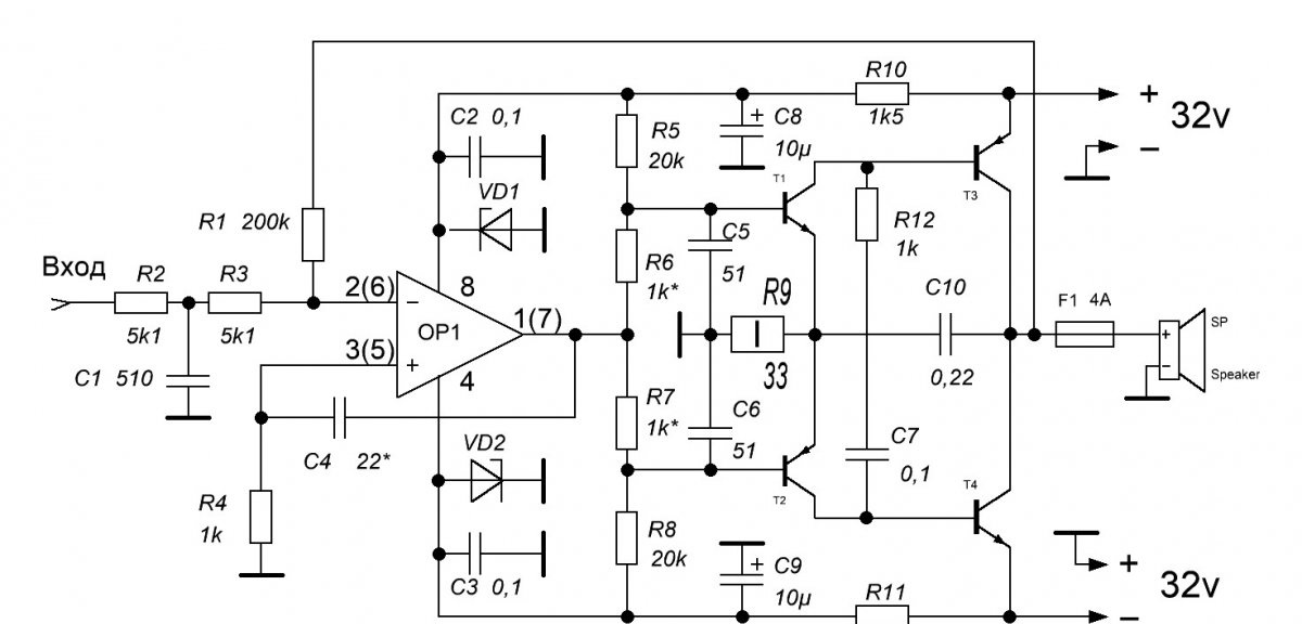
If the supply voltage of the converter of your amplifier is not +/- 32 volts, but less (for example +/- 24 volts), then the output power of the amplifier will be less. This situation can only be corrected by replacing the pulsed power transformer in the converter (or by rewinding its secondary winding to a larger number of turns) with replacing the filter capacitors and electrolytes also with a higher voltage. At a voltage of 32 volts, the output power is about 150 watts.With a lower voltage, for example 24 volts, the values of the resistors R10R11 should be reduced to 910 Ohms, other circuit changes will not be required. OP1 operational amplifier can be used of the type LM2904, LM324N, BA4558N, TL062 (072, 082) or any other similar, single or double (the numbering of the second channel in the case of the double amplifier is given in brackets in the diagram). For all the microcircuits listed above, the pinout is the same; when using other analogs, you should pay attention to the pinout (!).
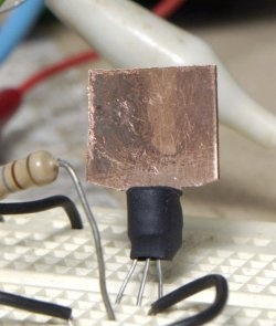
Zener diodes VD1VD2 - any, with a stabilization voltage of 15 volts (a typical power value for most op-amp circuits). Transistors T1T2 of the pre-terminal cascade type KT815G (817G) and KT814G (816G), respectively, or any of their foreign counterparts. These transistors need to be installed on small heat sinks. The circuit is not critical to the parts used and transistors do not require special selection by parameters. It is better to put T3T4 output transistors more powerful, for example, type 2SA1943 and 2SC5200. They are mounted on the housing (which acts as a heat sink) through electrical insulating gaskets made of mica or special heat-conducting material. All resistors with power from 0.25 watts, except for R9 - it will heat up very much at high powers and it is better to put it with a power of at least 2 watts. Capacitors - of any type, with an operating voltage of not less than the supply voltage, and preferably 50-63 volts. When setting up, it is necessary to select the values of the R6R7 resistances in such a way that in the "rest" mode and with the speaker turned off, the DC voltage on the bases of transistors T1 and T2 is on the order of 0.4-0.6 volts. Capacitors C4, C5C6 and C7 are responsible for the stability of the circuit to self-excitation by RF and are selected in the event of such excitations. With the correct layout of the tracks of the printed circuit board, no excitations, as a rule, are observed. Resistor R1 sets the feedback depth and determines the overall gain of the amplifier.
Strongly overestimating its rating is undesirable, as this can also lead to instability of the amplifier. The diagram indicates its optimal value.
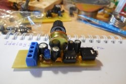
Channel adder and adjustable filter unit
This block is also assembled according to a rather simple "classical scheme":
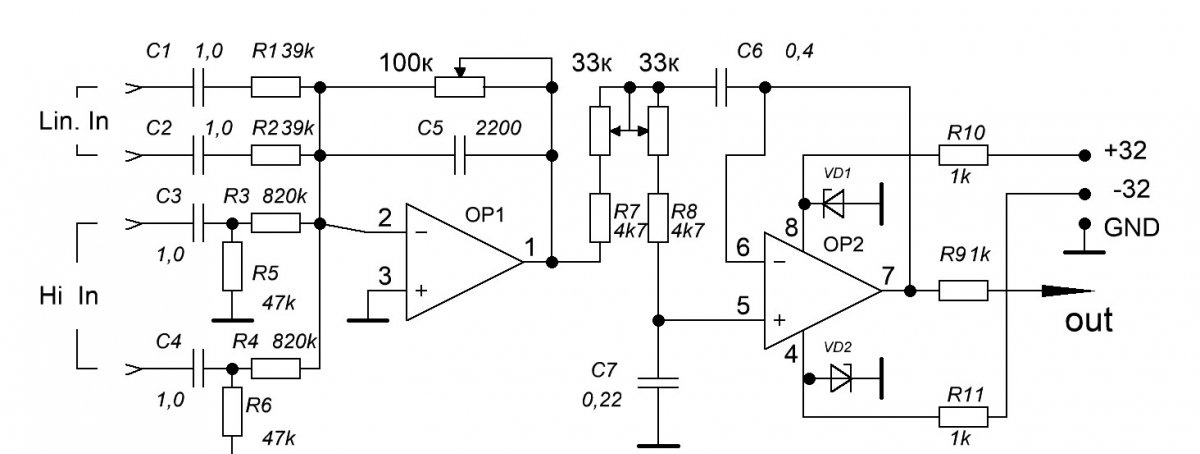
The circuit has a regular line input (Line In) and a high level input (Hi In). A high-level input is designed to connect the entire amplifier directly to speakers that work, for example, from another amplifier and are used if there are no linear outputs in the car radio. If such an input is not intended to be used, then the elements C3C4R3R4R5R6 can be excluded from the circuit. A 100 kΩ variable resistor controls the gain of the cascade and is output to the front panel of the housing as a “Level” regulator. It can be replaced with a nominal value from 50 to 200 kOhm and connected to the board with a necessarily shielded wire (!). A dual 33 kΩ resistor controls the cutoff frequency of the filter (from 50 to 500 Hz) and can be replaced by a nominal value from 22 to 56 kΩ. It is also displayed on the front panel of the case and connected to the board with a wire in the screen. The operational amplifiers here can be the same as in the power amplifier and the Zener diodes VD1VD2 too. With proper assembly and serviceable parts, this scheme does not require any adjustment.
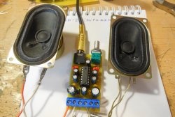
As a result, we get a workable amplifier for a subwoofer with quite decent parameters and power. All the schemes used here were repeated more than once and showed high reliability, much higher than the "native" for this car amplifier - Chinese ...