Quite often, residents of apartment buildings need to fix a picture, a hanger, a shelf, or some other piece of furniture on the wall of an apartment. To do this, mark a point on the wall and drill a small hole with a perforator. However, there is always a chance to get into the wiring hidden in the wall under the wallpaper - in this case, a small update to the interior can end with the inevitable call of electricians. To prevent this from happening, you can assemble a simple hidden wiring detector that will accurately show where the wires go and where they don't.
Scheme
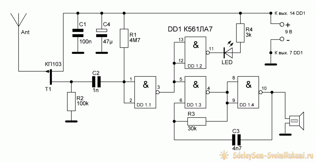
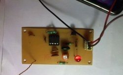
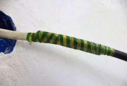
A sensitive element of the circuit is a KP103 field-effect transistor, to the gate of which an antenna is connected. You can use the transistor in any case and with any letter index. The device responds to wires under a voltage of 220 V 50 Hz, regardless of whether current flows through them or not. The circuit also uses the K561LA7 chip, which represents 4 logical elements 2I-NOT. It can be replaced by an imported analog, the CD4011 chip. The LED on the circuit lights up when the antenna is in close proximity to the live wire. As an antenna, you can use a segment of an ordinary thin wire, 5-10 cm long. The longer its length, the greater the sensitivity of the device. The circuit consumes approximately 10-15 mA, is powered by a voltage of 9 volts. An ordinary Crohn battery is suitable for power. If necessary, any piezoelectric radiator, for example, ЗП-3, can be connected to the 10th output of the microcircuit, then a sound will be heard when a wire is detected.
You can download the board here:
[29.96 Kb] (downloads: 2129)

Detector assembly
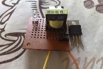
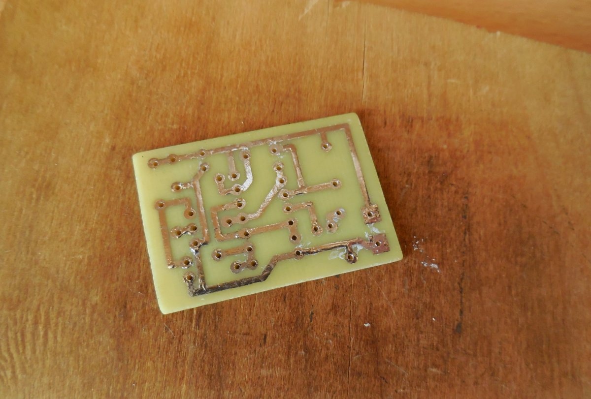
The circuit is assembled on a miniature printed circuit board measuring 40 x 30 mm, which can be done by the LUT method. The printed circuit board is completely ready for printing, you do not need to mirror it. After etching, it is desirable to tin the paths, this will simplify the soldering of parts, and copper will not oxidize.
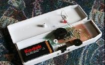
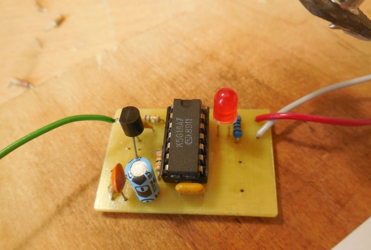
After manufacturing the printed circuit board, you can solder the parts. You should be careful when handling the microcircuit - it is sensitive to static and can easily be damaged. Therefore, on the board we solder the socket under the microcircuit and place the microcircuit in it only after the assembly is completed. You also need to be careful when soldering a transistor - if it is in a plastic case, then only two legs are soldered to the board - the drain and the source, and the antenna is soldered directly to the gate. If the case is metal, all three legs are soldered to the board along with the antenna. It is important not to mix up the pin, otherwise the device will not work. Power wires, for convenience, you can immediately solder to the connector for Krona, as I did. After soldering is completed, it is necessary to wash off the flux residues from the board, otherwise sensitivity may suffer. It is also advisable to check the correct installation and adjacent tracks for a short.


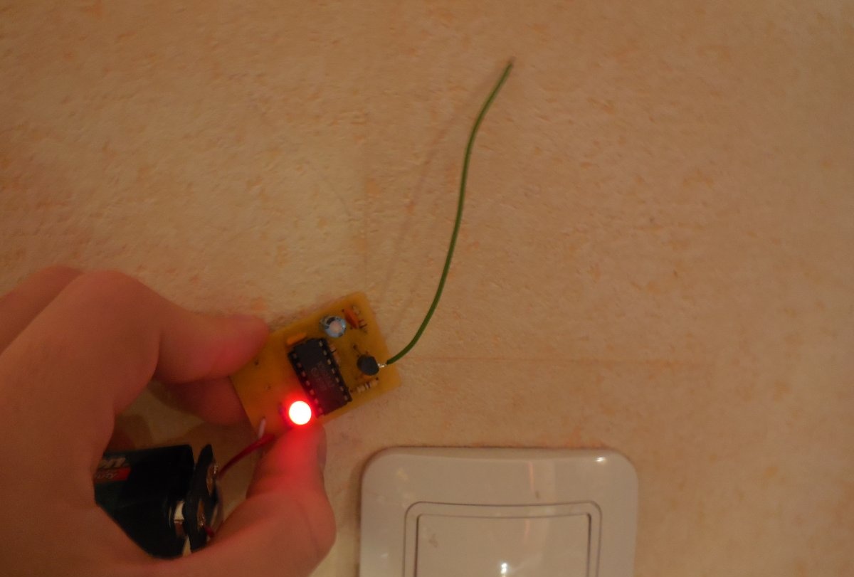
Detector tests
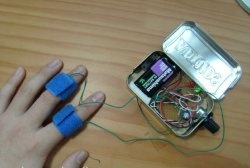
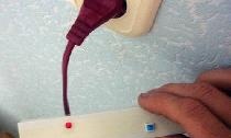
After the assembly is complete, you can proceed with the tests. We take the crown and connect it to the board, putting an ammeter in the gap of one of the wires. The consumption of the circuit should be 10-15 mA. If the current is normal, you can bring the detector antenna to any network wire and observe how the LED will light up and beep the piezo emitter, if installed. The wiring detection range is approximately 3-5 cm, depending on the length of the antenna. In this case, you should not touch the antenna, this significantly decreases the sensitivity. The device does not require any adjustment and starts working immediately after power is supplied. In addition to network wires, it also responds to twisted-pair cable. Successful assembly.
Watch the video
The video clearly shows how such a detector works. With its help, remoteness is enough to accurately determine where the wires from the switch go.