A radio bug is a simple radio transmitter with a microphone that picks up the smallest sounds around you and transmits them through a radio wave. Thus, leaving such a device in a suitable place, you can listen to everything that is done around it. You can find many applications of the radio bug - for example, use it as a baby monitor, wireless headphones or just to eavesdrop on someone else's conversations (such an application is not entirely legal). If you assemble two radio transmitters, then you can organize a wireless connection, for example, between neighboring houses. A large number of bug schemes are presented on the Internet, from the simplest to the most expensive and complex, built on microcircuits. The scheme below, in my opinion, is the most optimal: for its construction, rare or expensive parts are not required, but it provides a good signal transmission range (up to 500 m) and high stability.
Scheme
The circuit includes three cascades. A microphone audio signal amplifier is built on transistor VT1, a carrier signal generator is made on transistor VT2, and transistor VT3 is a high-frequency amplifier, it is he who is responsible for a good transmission range. The following transistors are used: VT1 - KT3130B, VT2 - KT368A, VT3 - KT3126B. An electret microphone is used to turn sound into an electrical signal. You can find one in any radio parts store, or drop it out of an unnecessary phone headset, because the right microphones are used there. Coil L1 is wound with a copper wire on a mandrel with a diameter of 3 mm, 6 turns, the wire can be taken with a cross section of 0.3-0.4 mm. As a mandrel, you can use a conventional drill. L2 is a choke with an inductance of 100 μH; it is best used ready-made. As an antenna, you can use a regular piece of wire, but if you need to achieve the maximum transmission distance, you need to use a wire with a length of one quarter of the wavelength at which the transmitter works.
[31.53 Kb] (downloads: 696)
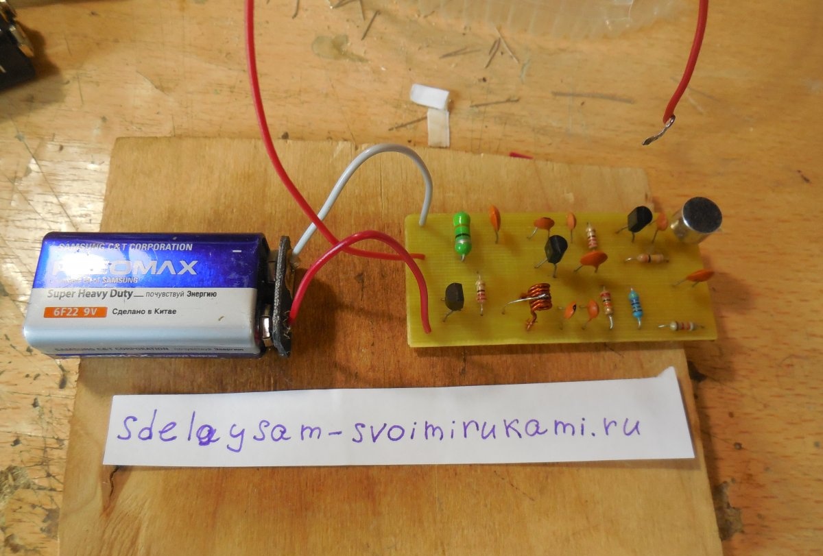
Build a radio bug
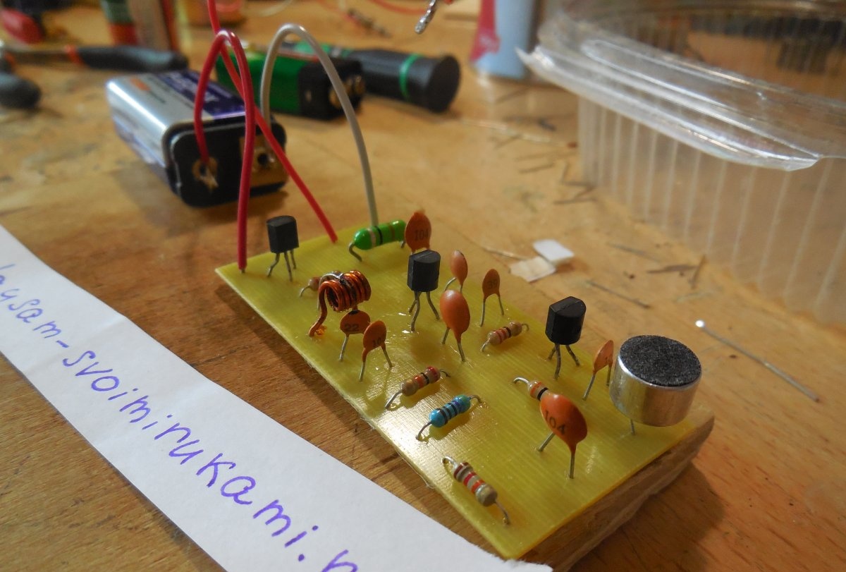
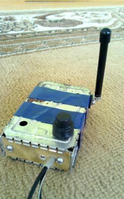
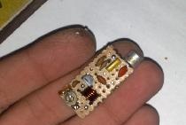
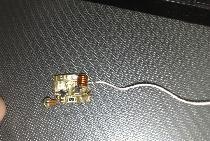
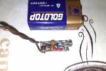
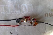
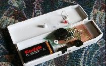
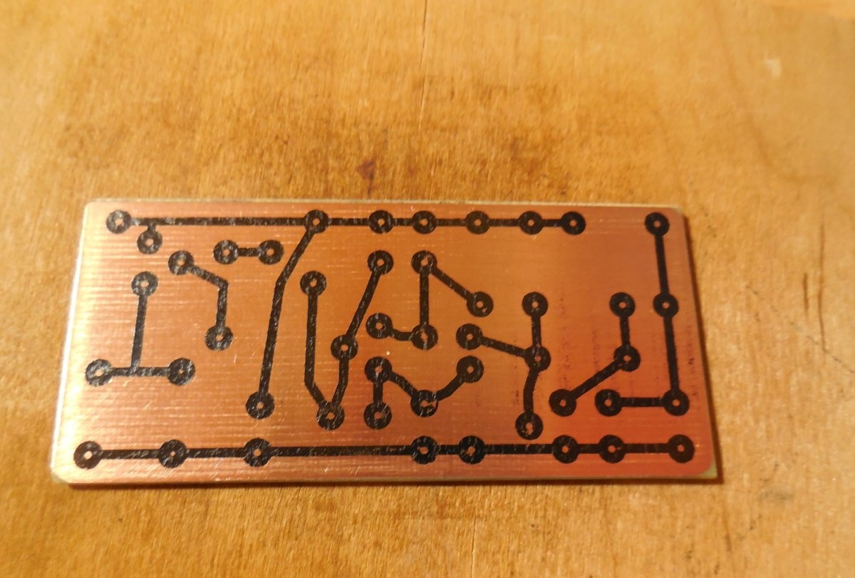
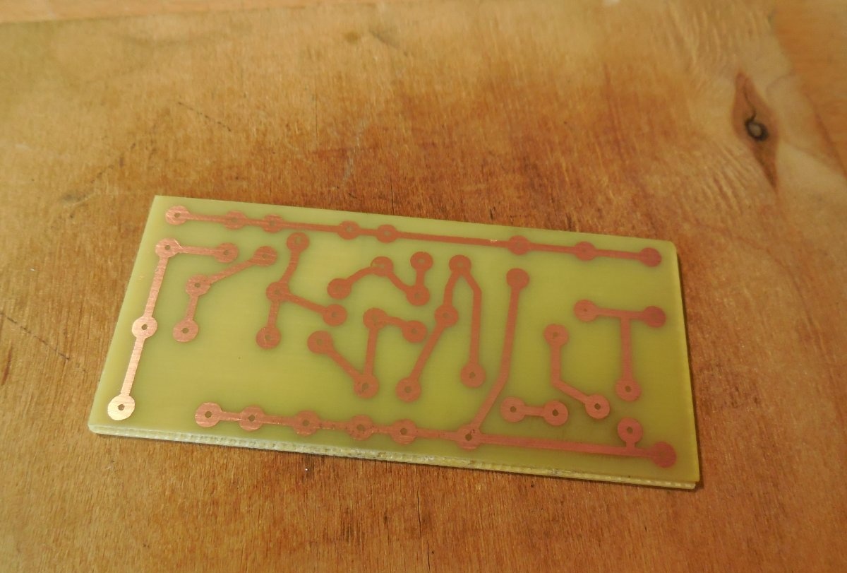
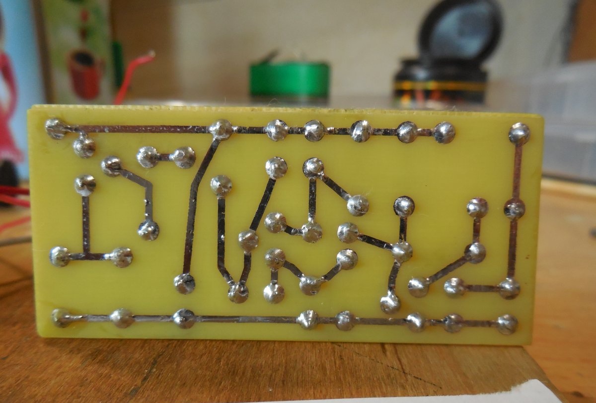
The circuit is assembled on a printed circuit board measuring 70 x 30 mm; the LUT method is used for its manufacture. It is not necessary to mirror the board before printing. Below are some photos of the process.
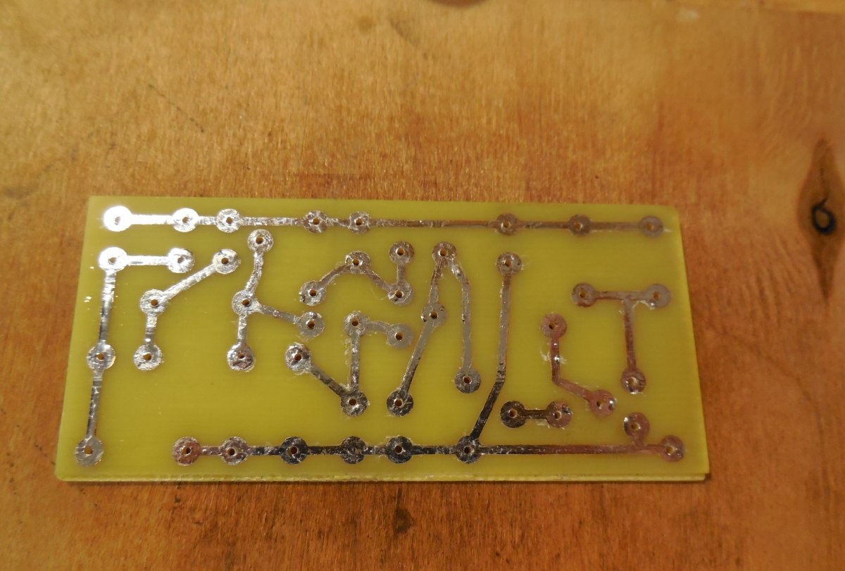
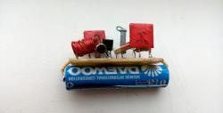
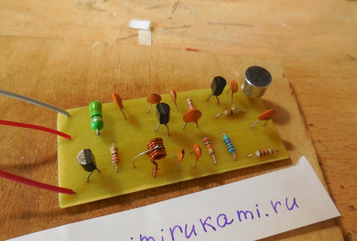
After the copper is etched, the holes are drilled, the paths are tinned, you can solder the parts. Particular attention should be paid to the microphone, or rather, its polarity. One of its contacts is short-circuited with its case - this contact is the negative one, it is soldered to the negative of the circuit. The microphone must be soldered quickly, otherwise there is a risk of overheating it. For convenience, the power wires can be soldered directly to the crown battery connector. Build a bug is not difficult, if you do everything gradually and do not rush, check the correct sealing of each part.
Setup and trial run
For the first start, you need a milliammeter, to control the current consumption, it is included in the gap of one of the supply wires. We connect the crown and look at the readings of the device - the current should lie within 10-30 mA. If it is normal, you can turn on the radio and try to find the signal of the transmitter under test. Most often, the signal already lies within 80-110 MHz. If he "crawled" outside this range and the receiver cannot catch him, you should adjust the coil L1, compressing and unclenching its turns. The frequency of the transmission depends on the inductance of this coil. When the signal is found, the coil can be filled with dielectric varnish or epoxy resin so that the setting does not go wrong.It is very important to ensure that the broadcast frequency of the assembled transmitter does not overlap with the frequency of any radio station. If they crossed, then you need to change the frequency by tuning the coil L1. No more tuning is required for the bug, just adjust the broadcast frequency. Now you can test it for the signal transmission range, moving farther and farther away from the transmitter with the pocket receiver. A correctly assembled and tuned transmitter can provide a transmission range of up to 500 m in an open area. Keep in mind that the reception range also depends on the sensitivity of the receiver. Successful assembly.