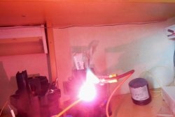
Induction heater allows you to heat the metal up to redness, without even touching it. The basis of such a heater is a coil in which a high frequency field is created, which acts on a metal object placed inside. High density current is induced in the metal, which causes the metal to heat up. Thus, to create an induction heater, you will need a circuit that generates high-frequency oscillations and the coil itself.
Scheme
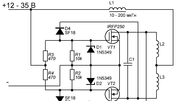
The above is a diagram of the universal ZVS driver, which is based on powerful field-effect transistors. It is best to use IRFP260, designed for a current of more than 40 A, but if you can’t get such, you can use IRFP250, they are also suitable for this circuit. D1 and D2 - zener diodes, you can apply any voltage of 12 to 16 volts. D3 and D4, ultrafast diodes, can be used, for example, SF18 or UF4007. It is advisable to take resistors R3 and R4 with a power of 3-5 watts, otherwise their heating is possible. L1 - inductor, you can take in the range of 10-200 μH. It must be wound with a sufficiently thick copper wire, otherwise its heating cannot be avoided. It is very simple to make it yourself - it is enough to wind 20-30 turns of wire with a cross section of 0.7-1 mm on any ferrite ring. Particular attention should be paid to capacitor C1 - it should be designed for a voltage of at least 250 volts. Capacitance can vary from 0.250 to 1 uF. A large current will flow through this capacitor, so it must be massive, otherwise its heating can not be avoided. L2 and L3 - this is the very coil inside which the heated object is placed. It represents 6-10 turns of thick copper wire on a mandrel with a diameter of 2-3 centimeters. On the coil, it is necessary to make a tap from the middle and connect it to the coil L1.
[47.33 Kb] (downloads: 409)
Heater circuit assembly
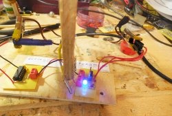
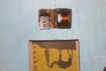
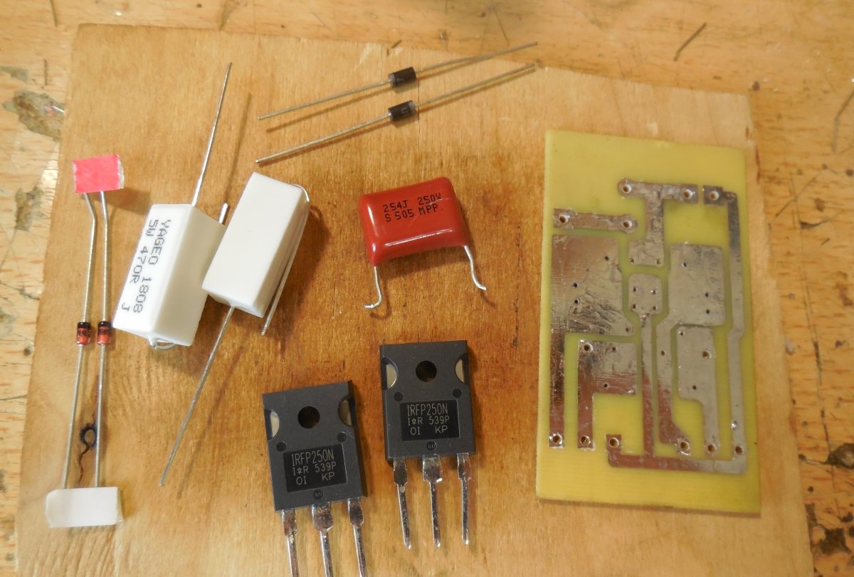
The scheme is assembled on a piece of PCB with dimensions of 60x40 mm. The PCB design is completely ready for printing and you do not need to mirror it. The board is made by the LUT method, below are some photos of the process.

After drilling the holes, the board must be tinned with a thick layer of solder for better conductivity of the tracks, because large currents will flow through them. As usual, first small parts, diodes, zener diodes and 10 kΩ resistors are soldered. Powerful 470 ohm resistors are installed on the board to save space. To connect the power wires, you can use the terminal strip, a place for it on the board is provided. After all parts have been sealed, the remaining flux must be washed off and the adjacent tracks checked for a short circuit.

Induction Coil Fabrication
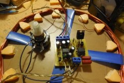
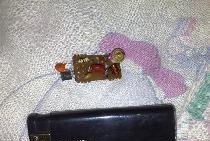
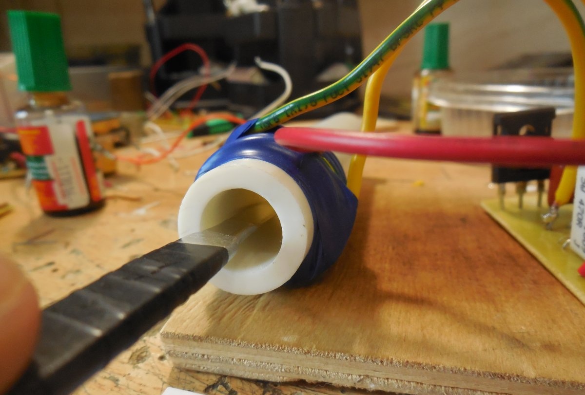
The coil is 6-10 turns of thick copper wire on a mandrel with a diameter of 2-3 centimeters, the mandrel must be dielectric. If the wire holds the shape well, you can completely do without it. I used a regular 1.5 mm wire and wound it around a piece of plastic pipe. An insulating tape is well suited for fastening coils.
A tap is made from the middle of the coil, you can simply remove the insulation from the wire and solder the third wire there, as I did. All wires must have a large cross section to avoid unnecessary losses.
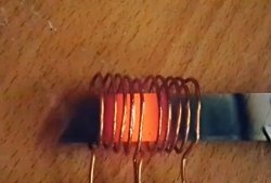
First start-up and heater tests
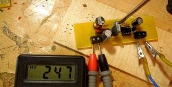
The supply voltage of the circuit lies in the range of 12-35 volts. The greater the voltage, the more the metal object heats up. But along with this, the heat generation on transistors also increases - if with a 12-volt power supply they hardly heat up, then with 30 volts they may already need a radiator with active cooling.You should also monitor the capacitor C1 - if it heats up significantly, then you should take a higher voltage, or assemble a battery of several capacitors. At the first start, you will need an ammeter, included in the gap of one of the supply wires. Idling, i.e. in the absence of a metal object inside the coil, the circuit consumes about 0.5 amperes. If the current is normal, you can put a metal object inside the coil and watch how it heats up literally in front of your eyes. Successful assembly.