Transistor amplifiers, despite the advent of more modern microcircuit amplifiers, have not lost their relevance. Getting a microcircuit is sometimes not so easy, but transistors can be removed from almost any electronic device, which is why avid radio amateurs sometimes accumulate mountains of these parts. In order to find a use for them, I propose to assemble a simple transistor power amplifier, the assembly of which even a beginner can master.
Scheme
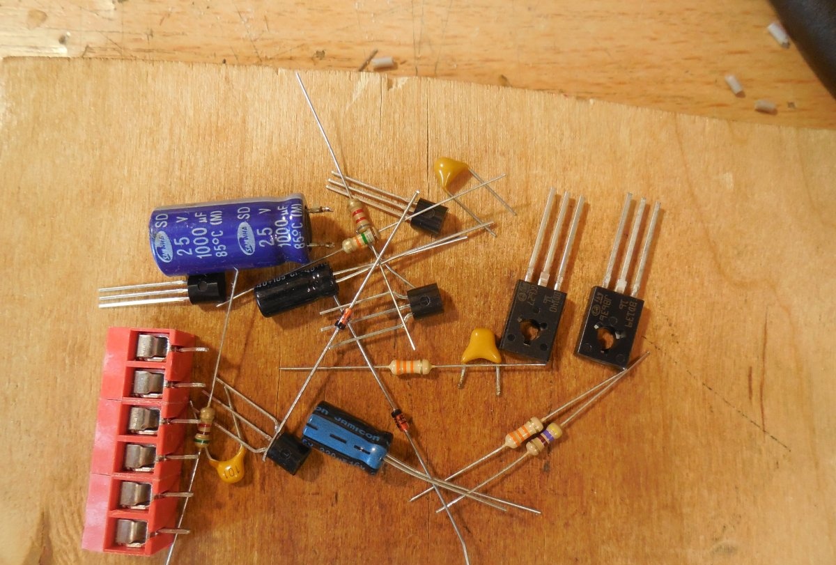
The circuit consists of 6 transistors and can develop power up to 3 watts when supplied with a voltage of 12 volts. This power is enough to sound a small room or workplace. Transistors T5 and T6 in the circuit form the output stage; in their place, the widely used domestic analogues KT814 and KT815 can be installed. Capacitor C4, which is connected to the collectors of the output transistors, separates the DC component of the output signal, which is why this amplifier can be used without a speaker protection board.Even if the amplifier fails during operation and a constant voltage appears at the output, it will not pass beyond this capacitor and the speakers of the speaker system will remain intact. It is better to use a film separating capacitor C1 at the input, but if you don’t have one at hand, a ceramic one will do. The analogues of diodes D1 and D2 in this circuit are 1N4007 or domestic KD522. The speaker can be used with a resistance of 4-16 Ohms; the lower its resistance, the more power the circuit will develop.
Amplifier assembly
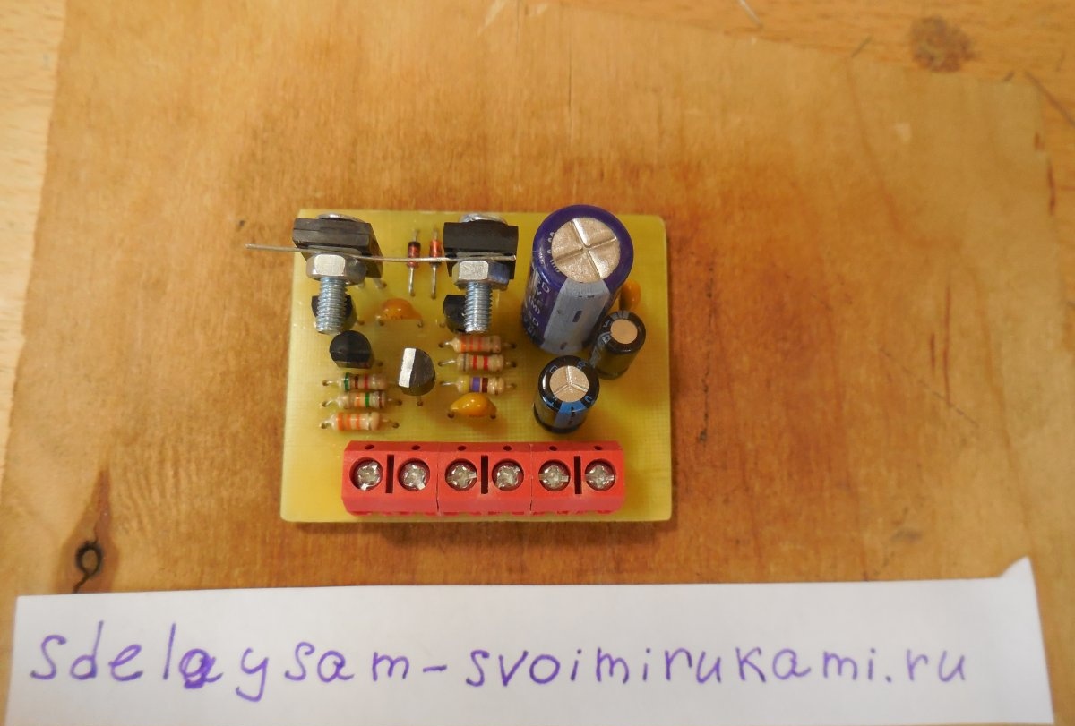
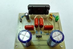
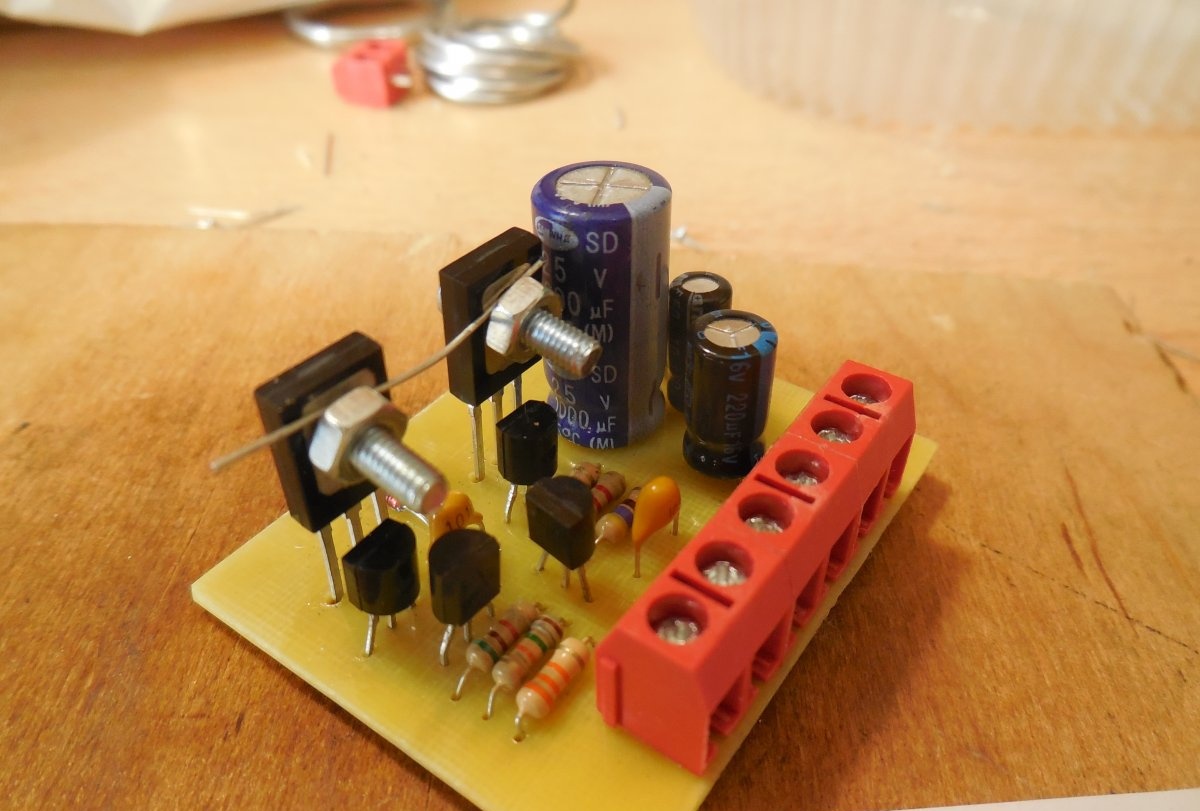
The circuit is assembled on a printed circuit board measuring 50x40 mm, a drawing in Sprint-Layout format is attached to the article. The given printed circuit board must be mirrored when printing. After etching and removing toner from the board, holes are drilled, it is best to use a 0.8 - 1 mm drill, and for holes for output transistors and a terminal block 1.2 mm.
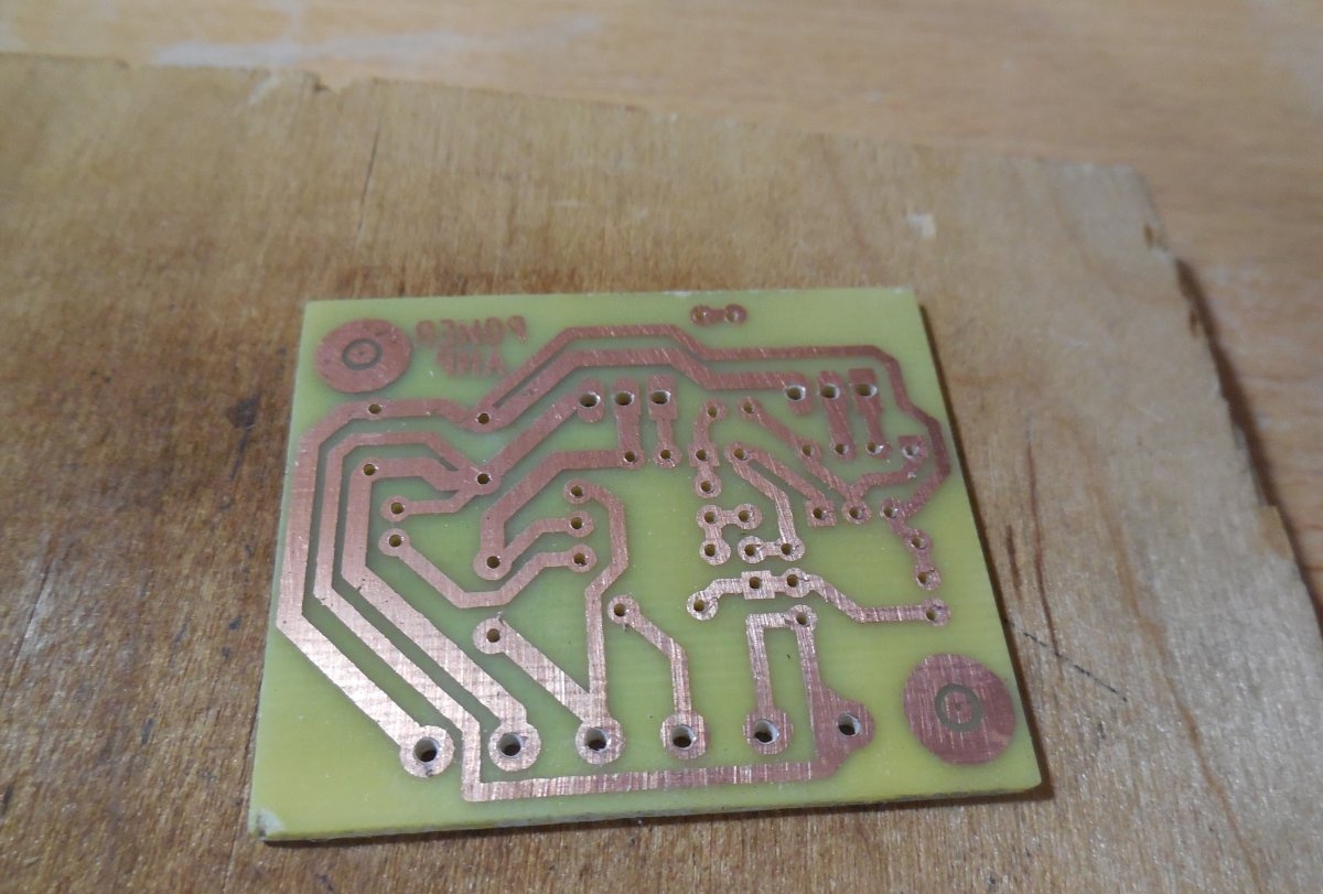
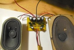
After drilling the holes, it is advisable to tin all the tracks, thereby reducing their resistance and protecting the copper from oxidation. Then small parts are soldered in - resistors, diodes, followed by output transistors, terminal block, capacitors. According to the diagram, the collectors of the output transistors must be connected; on this board, this connection occurs by shorting the “backs” of the transistors with a wire or a radiator, if one is used. A radiator must be installed if the circuit is loaded onto a speaker with a resistance of 4 Ohms, or if a high volume signal is supplied to the input. In other cases, the output transistors hardly heat up and do not require additional cooling.
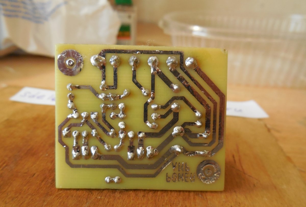
After assembly, be sure to wash off any remaining flux from the tracks and check the board for assembly errors or short circuits between adjacent tracks.
Amplifier setup and testing
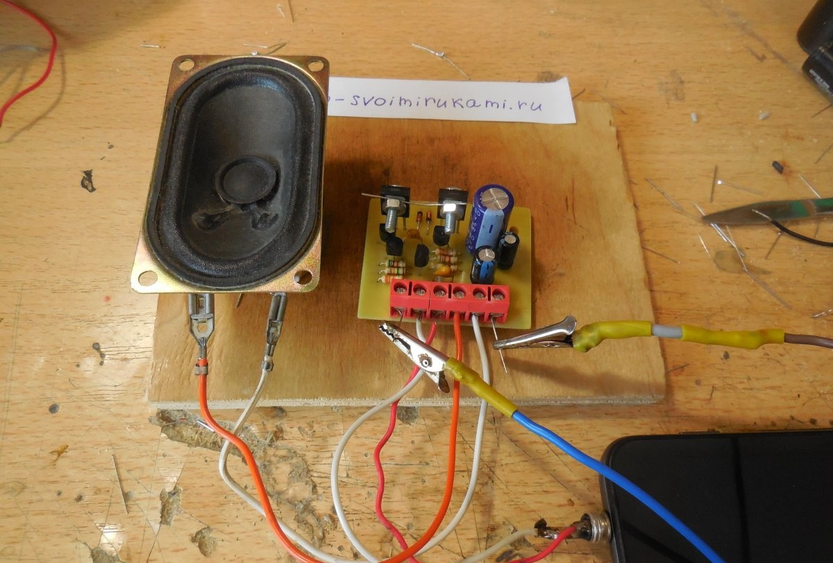
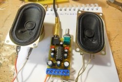
Once assembly is complete, you can apply power to the amplifier board. An ammeter must be connected to the gap in one of the supply wires to monitor the current consumption. We apply power and look at the ammeter readings; without applying a signal to the input, the amplifier should consume approximately 15-20 mA. The quiescent current is set by resistor R6; to increase it, you need to reduce the resistance of this resistor. The quiescent current should not be increased too much, because The heat generation on the output transistors will increase. If the quiescent current is normal, you can apply a signal to the input, for example, music from a computer, phone or player, connect a speaker to the output and start listening. Although the amplifier is simple in design, it provides very acceptable sound quality. To play two channels simultaneously, left and right, the circuit must be assembled twice. Please note that if the signal source is located far from the board, it must be connected with a shielded wire, otherwise interference and interference will not be avoided. Thus, this amplifier is completely universal due to its low current consumption and compact board size. It can be used both as part of computer speakers and when creating a small stationary music center. Happy assembly.