Do it yourself
Life hacks, master classes, useful tips, recipes.
home » Electronics » DIY amplifier » Speaker protection circuit

The Internet now offers a huge number of different sound amplifiers, for every taste and color, to suit any need. As you know, even the most reliable amplifiers tend to fail, for example, due to improper operating conditions, overheating or incorrect connection. In this case, there is a high probability that the high supply voltage will end up at the output of the amplifier, and, therefore, will easily end up directly on the speakers of the speaker system. Thus, a failed amplifier drags with it “to another world” the speaker system connected to it, which can cost much more than the amplifier itself. That is why it is highly recommended to connect the amplifier to the speakers through a special board called speaker protection.
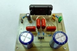
Scheme

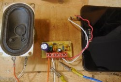
One of the options for such protection is shown in the diagram above. The protection works as follows: the signal from the amplifier output is supplied to the IN input, and the speakers are connected to the OUT output. The negative of the amplifier is connected to the negative of the protection circuit and goes directly to the speakers.In the normal state, when the amplifier is working and power is supplied to the protection board, relay Rel 1 closes the input of the board to the output and the signal goes directly from the amplifier to the speakers. But as soon as a constant voltage of at least 2-3 volts appears at the input, the protection is triggered, the relay is turned off, thereby disconnecting the amplifier from the speakers. The circuit is not critical to resistor values ​​and allows for variation. Transistor T1 can be used 2N5551, 2N5833, BC547, KT3102 or any other low-power npn transistor. T2 must be composite with a high gain, for example, BDX53 or KT829G. Light-emitting diode in the diagram serves to indicate the state of the relay. When it is on, the relay is on, the signal goes directly from the amplifier to the speakers. In addition to protection against DC voltage, the circuit provides a delay in connecting the speaker system. After applying the supply voltage, the relay does not turn on immediately, but after 2-3 seconds, this is necessary in order to avoid clicks in the speakers when the amplifier is turned on. The supply voltage of the circuit is 12 volts. Any relay can be used with a winding supply voltage of 12 volts and a maximum current through the contacts of at least 10 amperes. The S1 latching button is located on the wires; it is needed to force the relay to turn off, just in case. If this is not required, you can simply short-circuit the tracks on the PCB.

shema-zaschity-akusticheskih-sistem.zip [46.57 Kb] (downloads: 1689)

Assembling the device

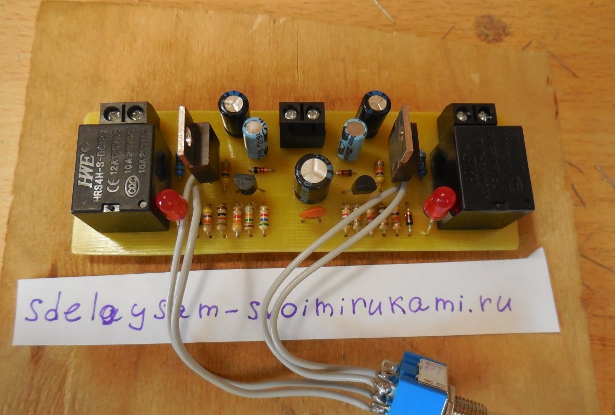
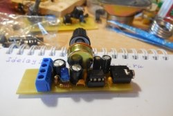
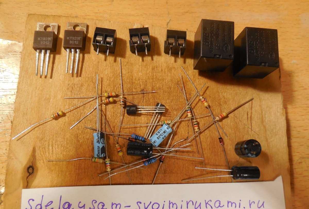
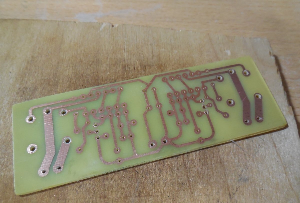
Amplifiers are most often designed for two channels, left and right, so the protection circuit must be repeated twice for each channel. For convenience, the board is laid out so that it already provides for the assembly of two identical circuits at once. The printed circuit board is manufactured using the LUT method, its dimensions are 100 x 35 mm.

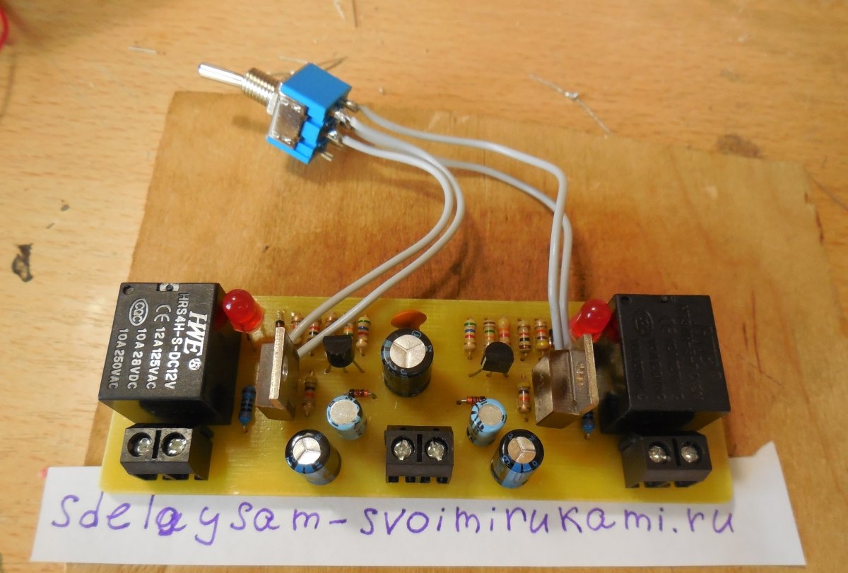
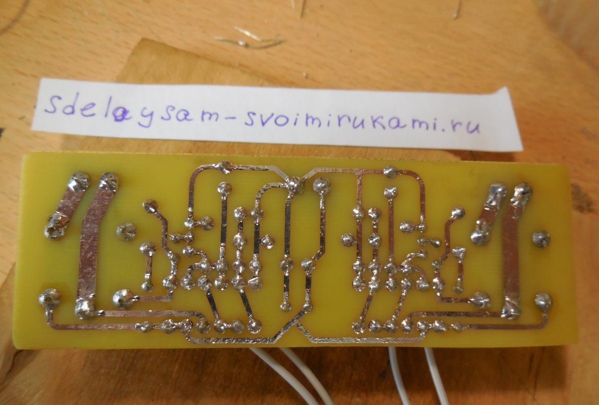
After drilling the holes, it is advisable to tin the paths. Now you can start soldering the parts. Particular attention should be paid to the pinout of the transistors; it is very important not to confuse it and solder the transistors on the right side. As usual, small parts are soldered first - resistors, diodes, capacitors, and only then transistors, terminal blocks, and, last but not least, massive relays. To connect all wires, you can use terminal blocks, the places for which are provided on the board. After soldering is completed, you need to wash off the remaining flux from the tracks and check the correct installation.
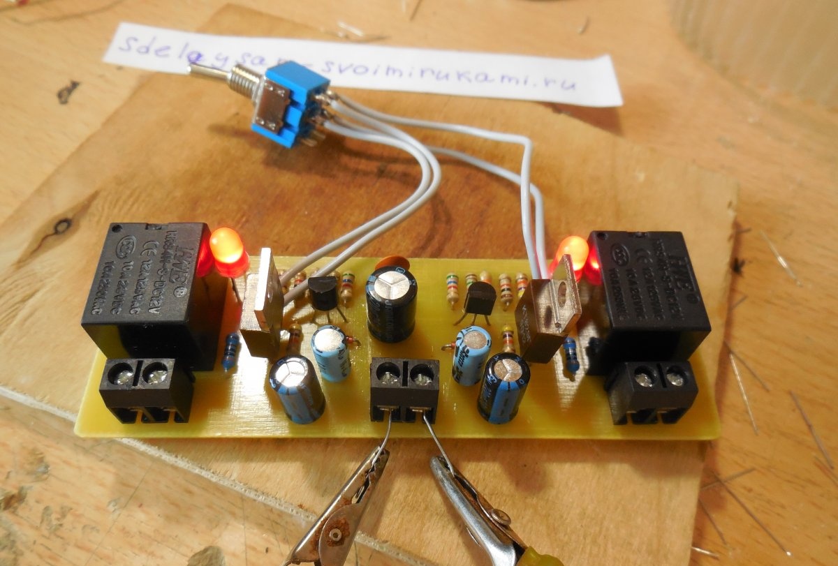
Protection tests

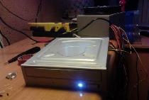
Now that the board is completely ready, we can begin testing. We supply power to the circuit (12 volts), after two seconds the relay should simultaneously click and turn on LEDs. Now we take some kind of constant voltage source, for example, a battery, and connect it between the minus of the circuit and the input. The relay should turn off immediately. We remove the battery and the relay turns on again. You can connect a battery by changing its polarity; the circuit operates regardless of what polarity the voltage appears at its input. We perform the same manipulations with the second circuit located on the same board. The protection threshold is approximately 2 volts. Now that the protection board has been tested, you can connect it to the amplifier and not be afraid that the speakers in expensive speakers will deteriorate due to the amplifier breaking down. Happy assembly.

come back
Comment
  • bowtiesmilelaughingblushsmileyrelaxed relaxedsmirk
    heart_eyeskissing_heartkissing_closed_eyesflushedrelievedsatisfiedgrin
    winkstuck_out_tongue_winking_eyestuck_out_tongue_closed_eyesgrinningkissingstuck_out_tonguesleeping
    worriedfrowninganguishedopen_mouthgrimacingconfusedhushed
    expressionlessunamusedsweat_smilesweatdisappointed_relievedwearypassive
    disappointedconfoundedfearfulcold_sweatperseverecrysob
    joyastonishedscreamtired_faceangryragetriumph
    sleepyyummasksunglassesdizzy_faceimpsmiling_imp
    neutral_faceno_mouthinnocent
3+three=
Comments (10)
  1. Guest Oleg
    #1 Guest Oleg Guests 20 August 2018 19:45
    1
    “In this case, there is a high probability that a high supply voltage will be at the output of the amplifier.”
    In fact, the probability of this event approaches zero. In 20 years of practice, repairs have never occurred.
    1. Andrew
      #2 Andrew Guests 2 August 2019 16:52
      2
      During the manufacture of a 40W power amplifier, a dozen speakers burned out for various reasons, and all because there was no protection. Whether you are an amateur or a pro in this matter. With the speakers, everything happens very quickly and you won’t have time to blink an eye.... But I feel sorry for the speakers, very sorry.
  2. Ivan
    #3 Ivan Guests 28 June 2019 20:07
    1
    I assembled this diagram, although I placed it a little differently for myself. When power is applied, I measure 12 volts, but the relay cannot turn on. When the relay is connected, the voltage drops to 1 volt. There was no input signal. What can be wrong?
    1. Ivan
      #4 Ivan Guests 27 July 2019 19:14
      2
      When you made it for yourself, didn’t you mess up anything?
  3. Dmitriy
    #5 Dmitriy Guests 3 August 2019 15:35
    2
    The signet layout could be done for 2.1 acoustics
  4. Andrew
    #6 Andrew Guests 20 September 2019 16:09
    4
    I put together this circuit. It doesn’t work with the declared ratings; it doesn’t work with Upit = 12V. And why the hell should I install BDX53? In general, you can leave the power supply at 12V but select R5 (~20 kOhm). I have an onboard 15V and even in this case the relay did not work, R5 solved the problem. Instead of BDX53, KT819G and others like them work great. When powered by 15V, 15V relays are also required, but you can leave the 12V ones, they will get a little warm - it’s not a crime.With C2 = 220 µF the delay is 0.5-1 sec and not 2-3 sec as in the description, so you can and should increase the capacitance to 470 µF. Everything else works fine.
  5. Vadim
    #7 Vadim Guests 18 June 2020 17:19
    2
    Works great with declared ratings at Upit=12V
    BDX53 replaced with 2SD669
    thanks to the author
  6. Ruslan Shaikhadarov
    #8 Ruslan Shaikhadarov Guests 30 December 2021 14:04
    0
    I assembled it, but I didn’t have to put it together right away. When starting up, one relay started up without problems, a delay of about 1.5-2 seconds C2-470uF R5-47k The second one didn’t want to, C2-470uF with R5 had to be selected, stopped at 30k, a delay of about 1 sec started, I think, to equalize both channel 33k will be just right. This is with a power supply of 14 volts.
  7. Guest Dmitry
    #9 Guest Dmitry Guests May 25, 2022 00:20
    1
    With the declared ratings at Upit = 12V it works fine. BDX53 was replaced with 2SD669. On my own behalf, I will add that I increased C2 to 1000uf 16v, while turning on the relay to 5s, I also redrawn the board for the C945 transistor, I took it from the PC power supply, you can find it everywhere.
    Thanks to the author, it’s an excellent scheme, I’ll try it, it started the first time. blush
  8. Sergey
    #10 Sergey Guests 18 May 2023 16:33
    1
    I assembled the circuit, but the delay works fine if you turn off R3, otherwise the relay does not turn on. Why might this be?

Sensitive microphone for computer | Do it yourself

How to disinfect and remove odor from a cutting board

Insulating a room with polystyrene foam

Decorating a corner of a room with a tree branch | Do it yourself

«Do it yourself - with your own hands» - a site of interesting homemade products made from scrap materials and items at home. Step-by-step master classes with photos and descriptions, technologies, life hacks - everything a real master or just a craftsman needs for needlework. Crafts of any complexity, a large selection of directions and ideas for creativity.

We recommend reading

Washing machine error codes