Solid state relays have gained popularity recently. For many power electronics devices, solid state relays have become essential. Their advantage is a disproportionately large number of operations compared to electromagnetic relays and a high switching speed. With the ability to connect the load at the moment the voltage crosses zero, thereby avoiding heavy inrush currents. In some cases, their tightness also plays a positive role, but at the same time depriving the owner of such a relay the advantage of being able to repair it by replacing some parts. A solid-state relay, in case of failure, cannot be repaired and must be replaced entirely; this is its negative quality. The prices for such relays are somewhat steep, and it turns out to be wasteful.
Let's try together to make a solid-state relay with our own hands, preserving all the positive qualities, but without filling the circuit with resin or sealant, in order to be able to repair it in case of failure.
Scheme
Let's look at the diagram of this very useful and necessary device.
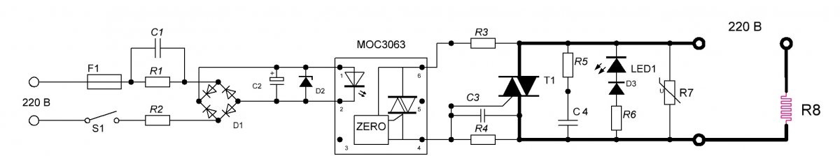
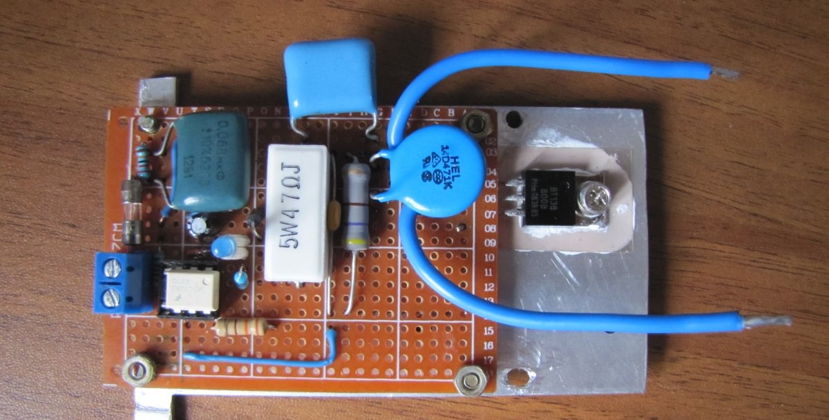
The basis of the circuit is the power triac T1 - BT138-800 for 16 Amperes and the optocoupler MOS3063 that controls it.The diagram shows in black the conductors that need to be laid with copper wire of a higher cross-section, depending on the planned load.
It is more convenient for me to control the optocoupler LED from 220 Volts, or from 12 or 5 Volts, as needed.
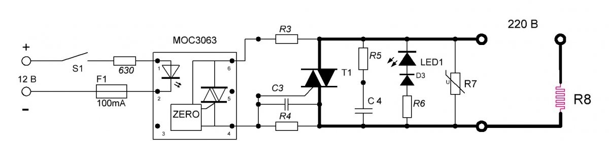
To control from 5 Volts, you need to change the 630 Ohm damping resistor to 360 Ohms, everything else is the same.
The ratings of the parts are calculated for MOS3063; if you use another optocoupler, then the ratings need to be recalculated.
Varistor R7 protects the circuit from voltage surges.
Indicator chain LED You can completely remove it, but it makes it clearer that the device is working.
Resistors R4, R5 and capacitors C3, C4 serve to prevent failure of the triac; their ratings are designed for a current of no more than 10 Amperes. If a relay is required for a large load, then the ratings need to be recalculated.
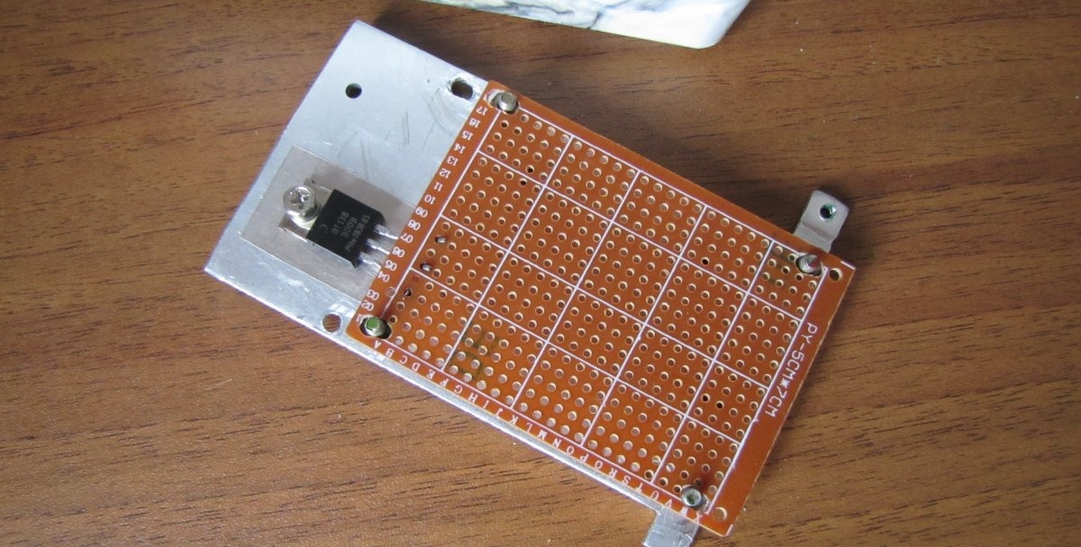
The cooling radiator for a triac directly depends on the load on it. With a power of three hundred watts, a radiator is not needed at all, and accordingly, the greater the load, the larger the radiator area. The less the triac overheats, the longer it will work and therefore even a cooling cooler will not be superfluous.
If you plan to control increased power, then the best solution would be to install a higher power triac, for example, VTA41, which is rated at 40 Amps, or similar. The part values will work without recalculation.
Parts and body
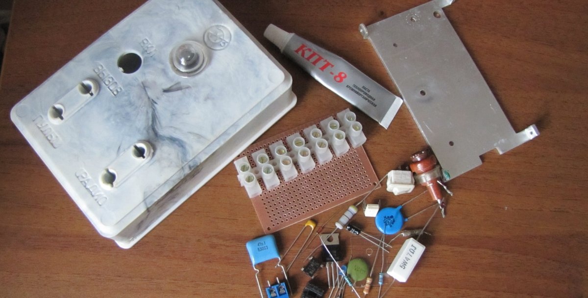
We will need:
- F1 - 100 mA fuse.
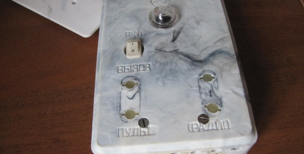
- S1 - any low-power switch.
- C1 – capacitor 0.063 uF 630 Volt.
- C2 – 10 - 100 µF 25 Volts.
- C3 – 2.7 nF 50 Volts.
- C4 – 0.047 uF 630 Volts.
- R1 – 470 kOhm 0.25 Watt.
- R2 – 100 Ohm 0.25 Watt.
- R3 – 330 Ohm 0.5 Watt.
- R4 – 470 Ohm 2 Watts.
- R5 – 47 Ohm 5 Watt.
- R6 – 470 kOhm 0.25 Watt.
- R7 – varistor TVR12471, or similar.
- R8 – load.
- D1 – any diode bridge with a voltage of at least 600 Volts, or assembled from four separate diodes, for example - 1N4007.
- D2 – 6.2 Volt zener diode.
- D3 – diode 1N4007.
- T1 – triac VT138-800.
- LED1 – any signal Light-emitting diode.
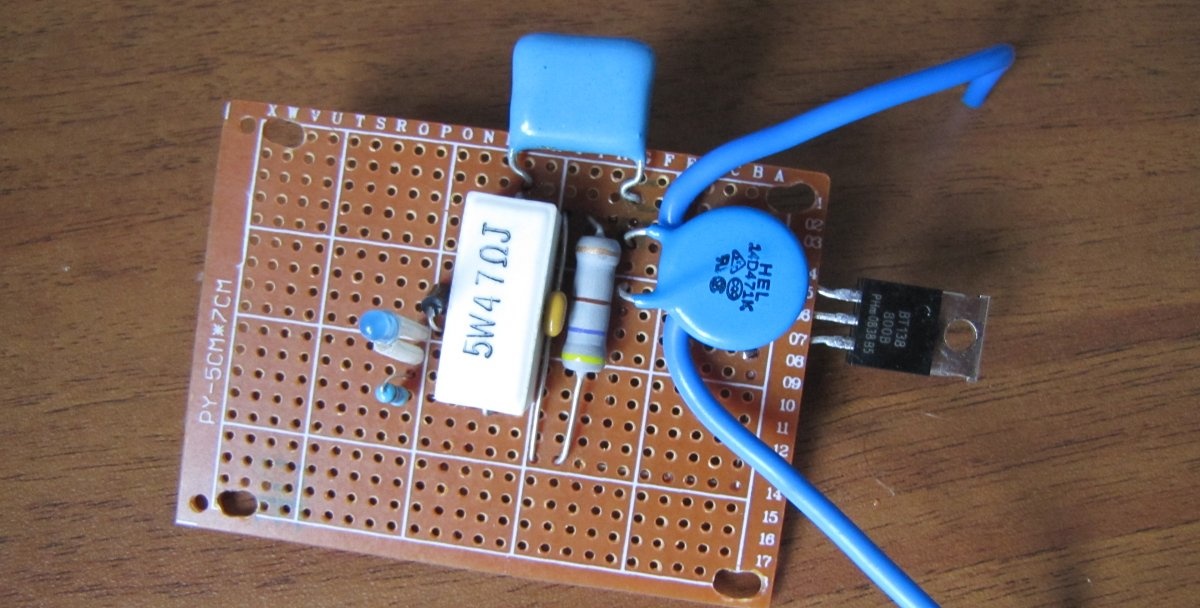
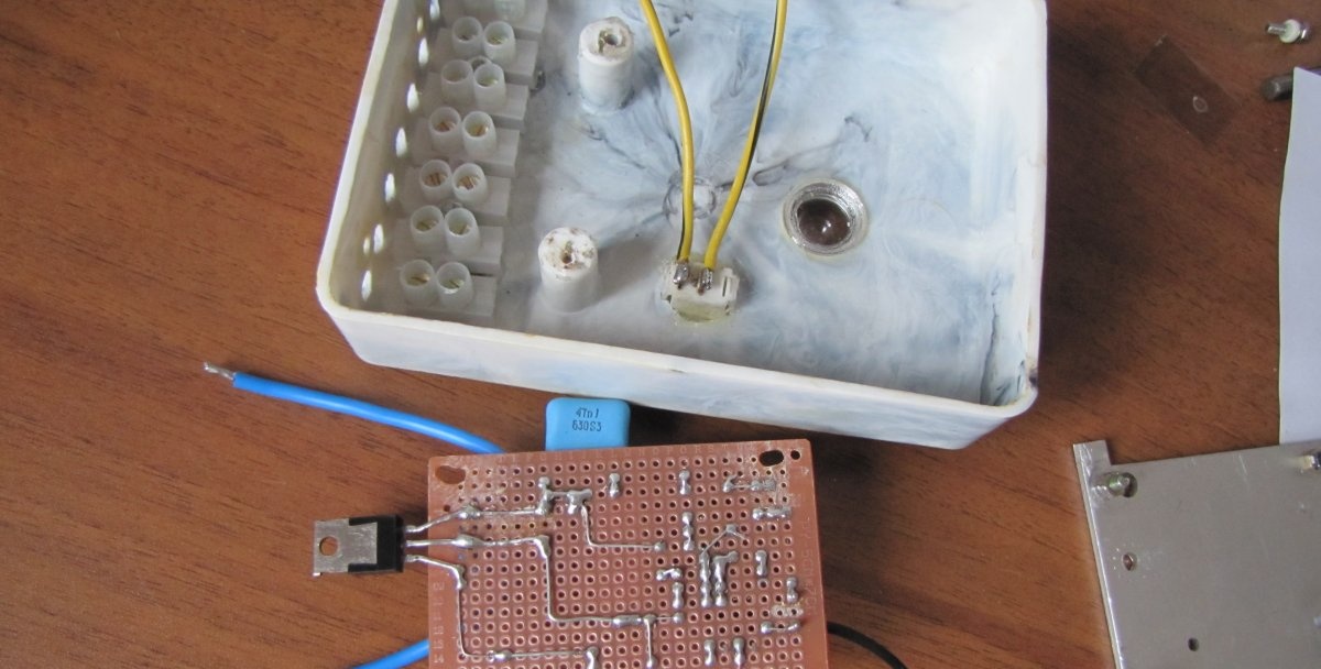
Making a solid state relay
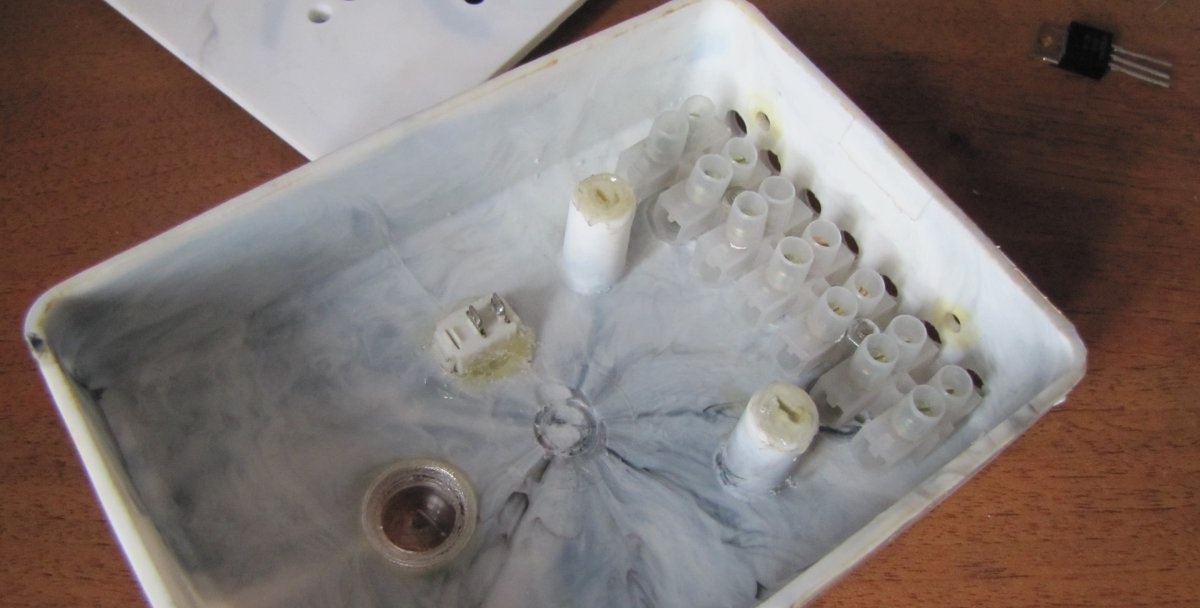
First, we outline the placement of the radiator, breadboard and other parts in the case and secure them in place.
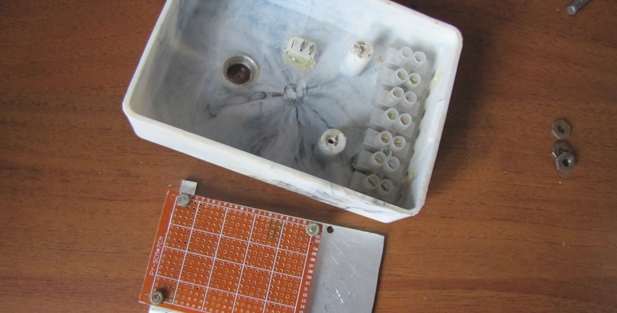
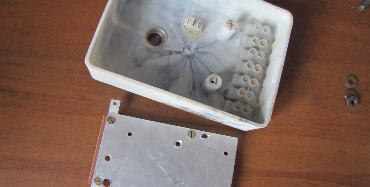
The triac must be insulated from the cooling radiator with a special heat-conducting plate using heat-conducting paste. The paste should come out slightly from under the triac when the fastening screw is tightened.
Next, place the following parts in accordance with the diagram and solder them.
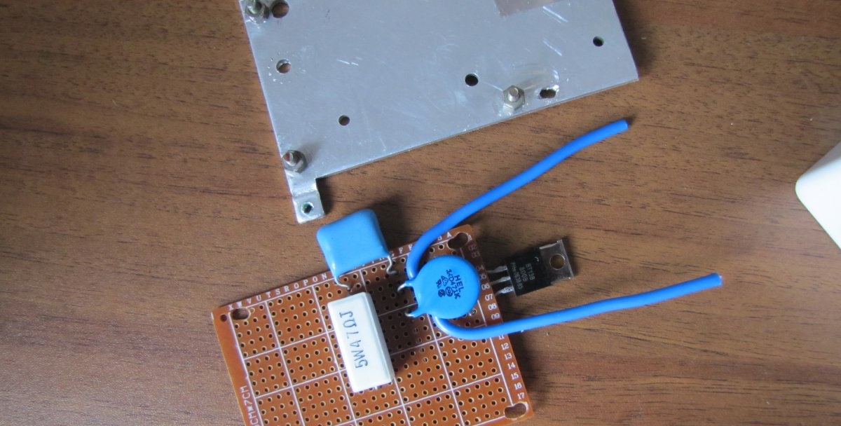
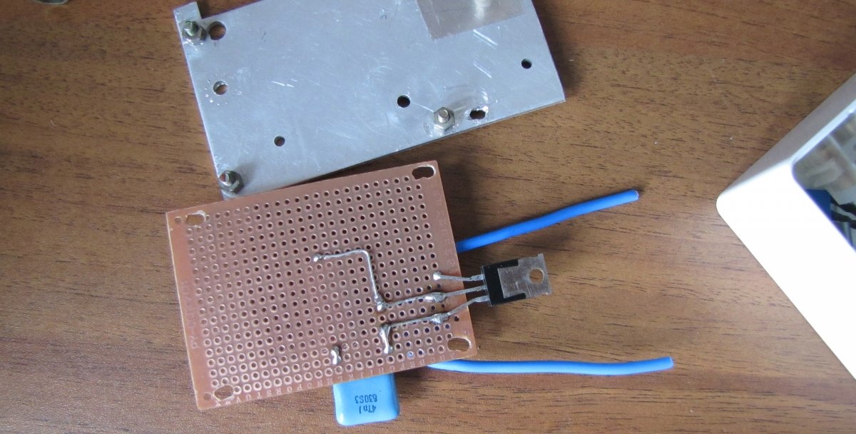
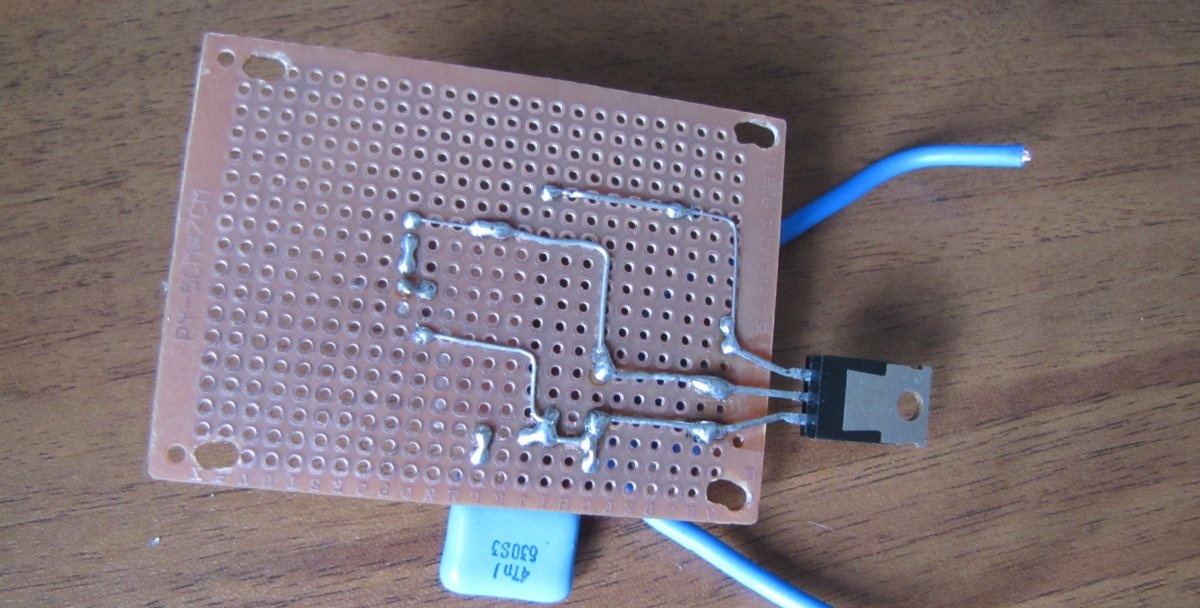
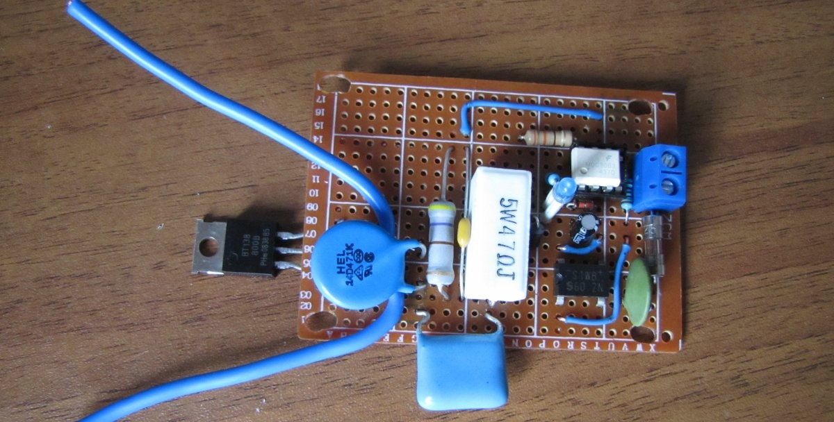
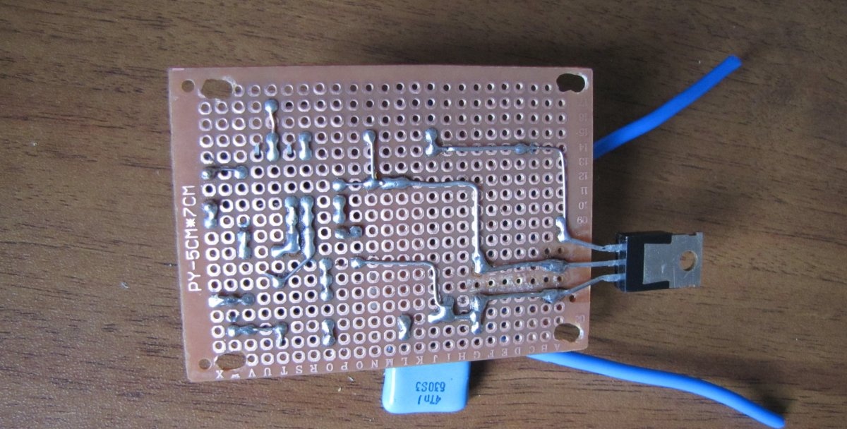
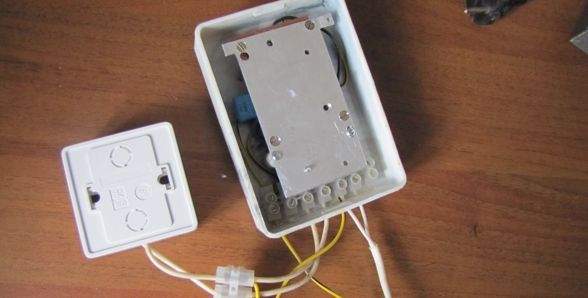
We solder the wires to connect the power and load.
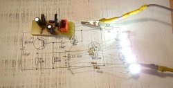
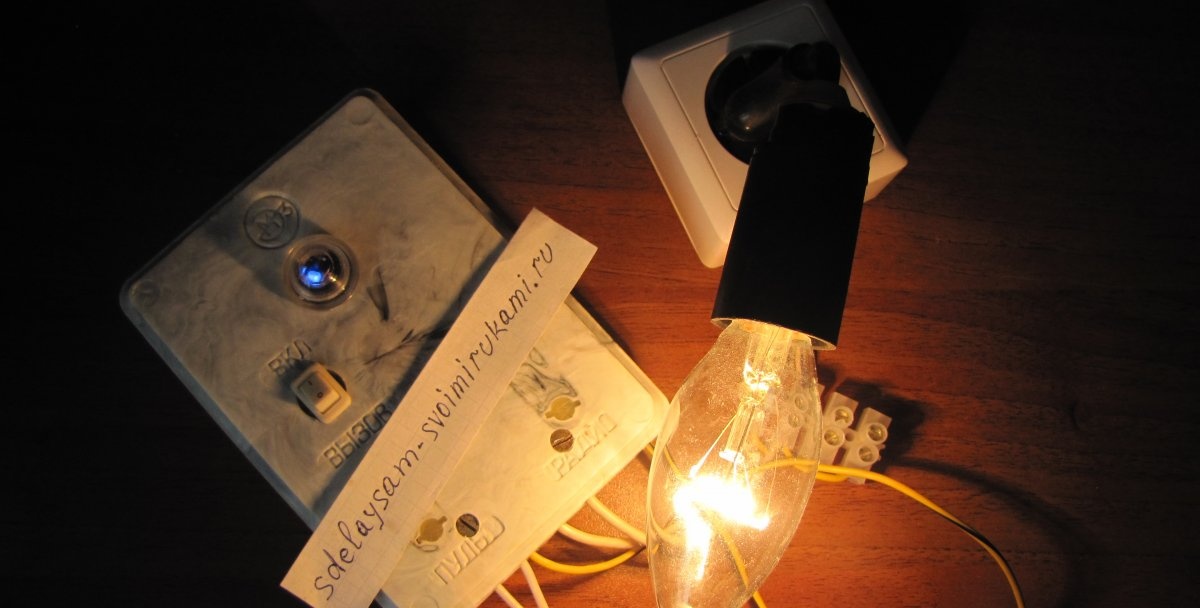
We place the device in the case, having previously tested it under minimal load.
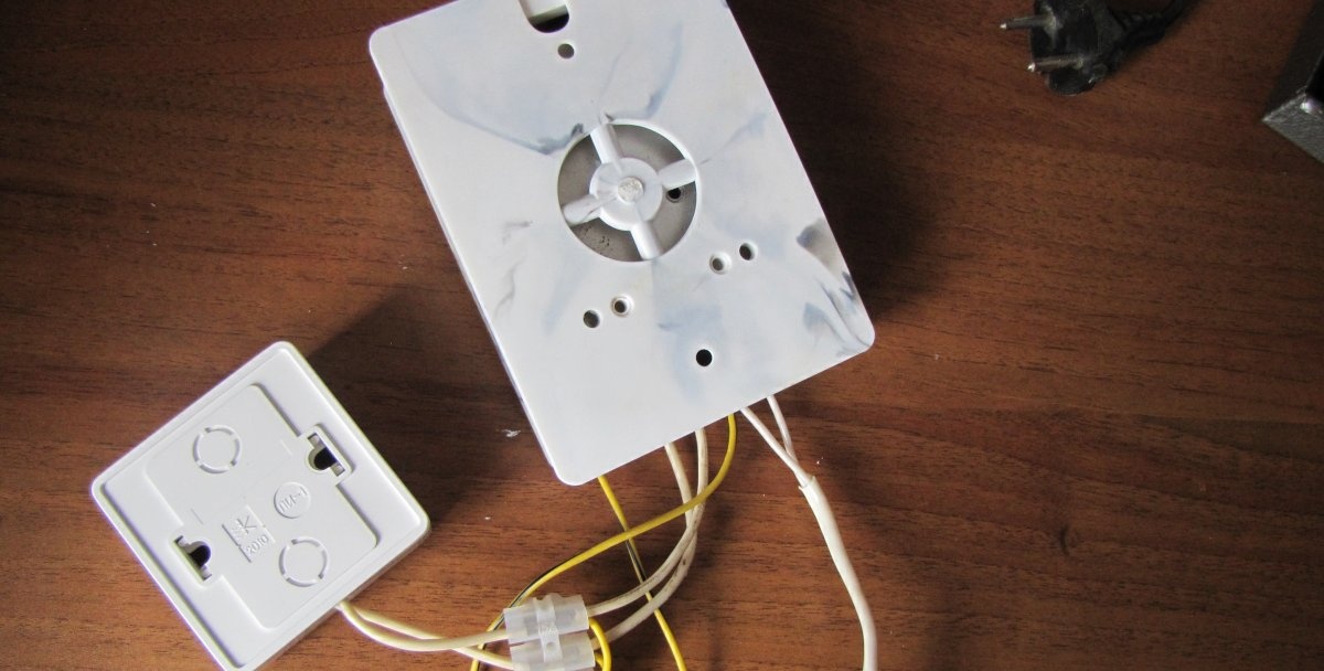
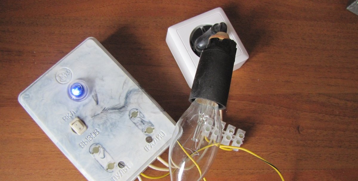
The test was successful.
Watch the video
Watch the video testing the device together with a digital temperature controller.