Electronic LATR
Currently, many voltage regulators are produced and most of them are made using thyristors and triacs, which create a significant level of radio interference. The proposed regulator does not produce interference at all and can be used to power various AC devices, without any restrictions, unlike triac and thyristor regulators.
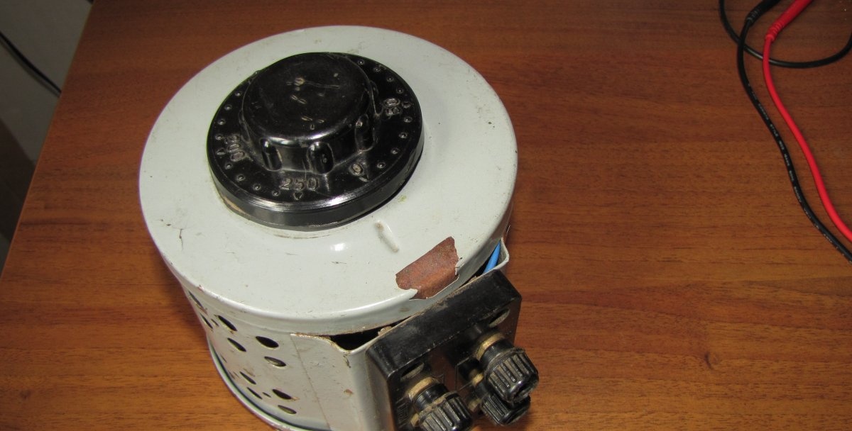
In the Soviet Union, a lot of autotransformers were produced, which were mainly used to increase the voltage in the home electrical network, when the voltage dropped very strongly in the evenings, and LATR (laboratory autotransformer) was the only salvation for people who wanted to watch TV. But the main thing about them is that at the output of this autotransformer the same correct sinusoid is obtained as at the input, regardless of the voltage. This property was actively used by radio amateurs.
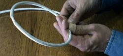
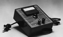
LATR looks like this:
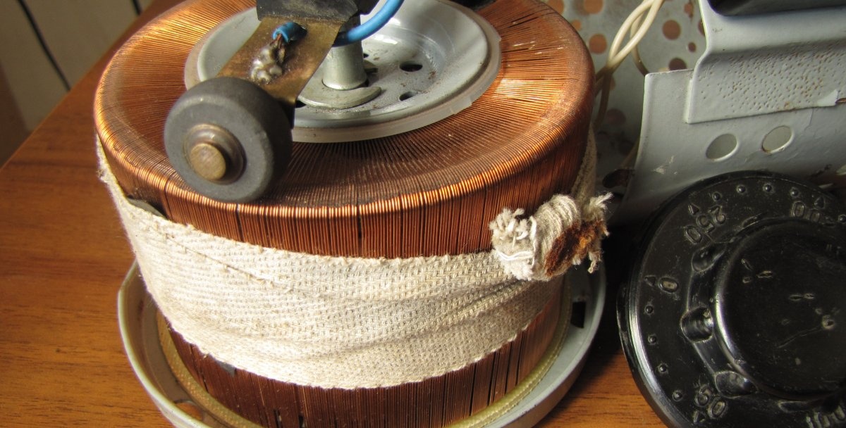
Interference in such a LATR was still due to sparking at the moment the roller rolled along the windings.
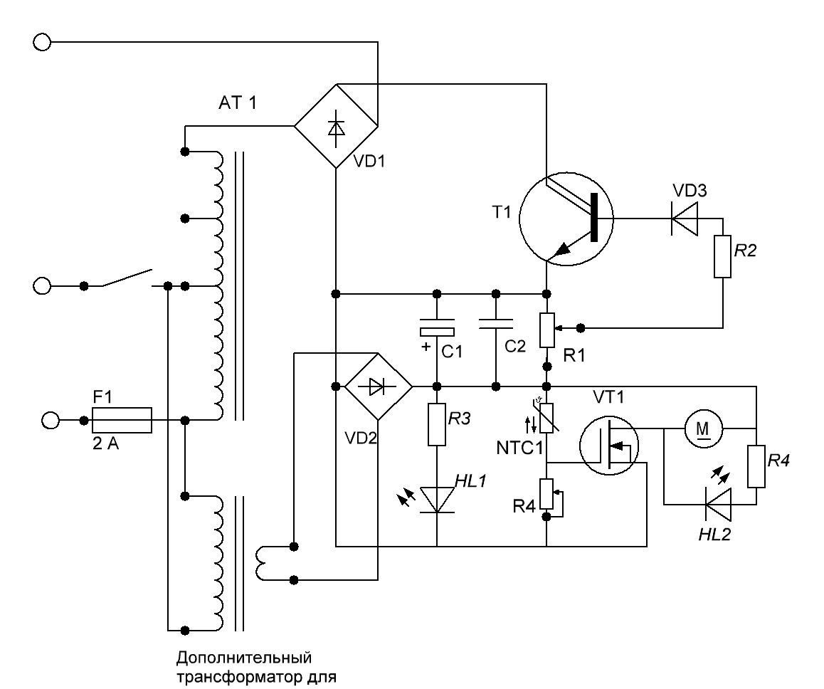
In the magazine “RADIO”, No. 11, 1999, on page 40, the article “Interference-free voltage regulator” was published.
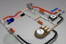
Diagram of this regulator from the magazine:
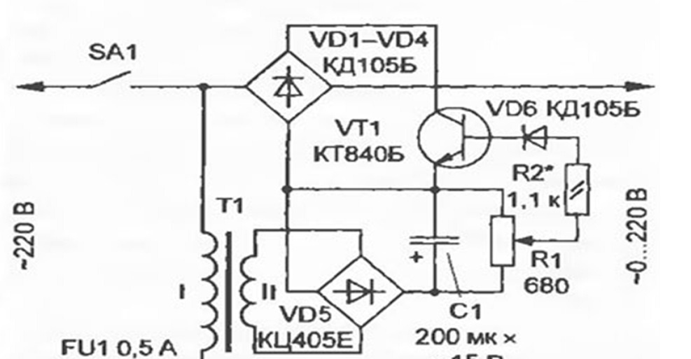
The regulator proposed by the magazine does not distort the shape of the output signal, but the low efficiency and the inability to obtain increased voltage (above the mains voltage), as well as outdated components that are difficult to find today, negate all the advantages of this device.
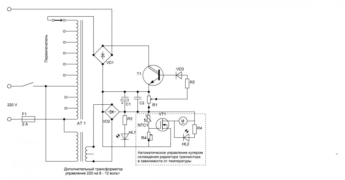
Electronic LATR circuit diagram
I decided, if possible, to get rid of some of the disadvantages of the regulators listed above and preserve their main advantages.
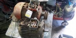
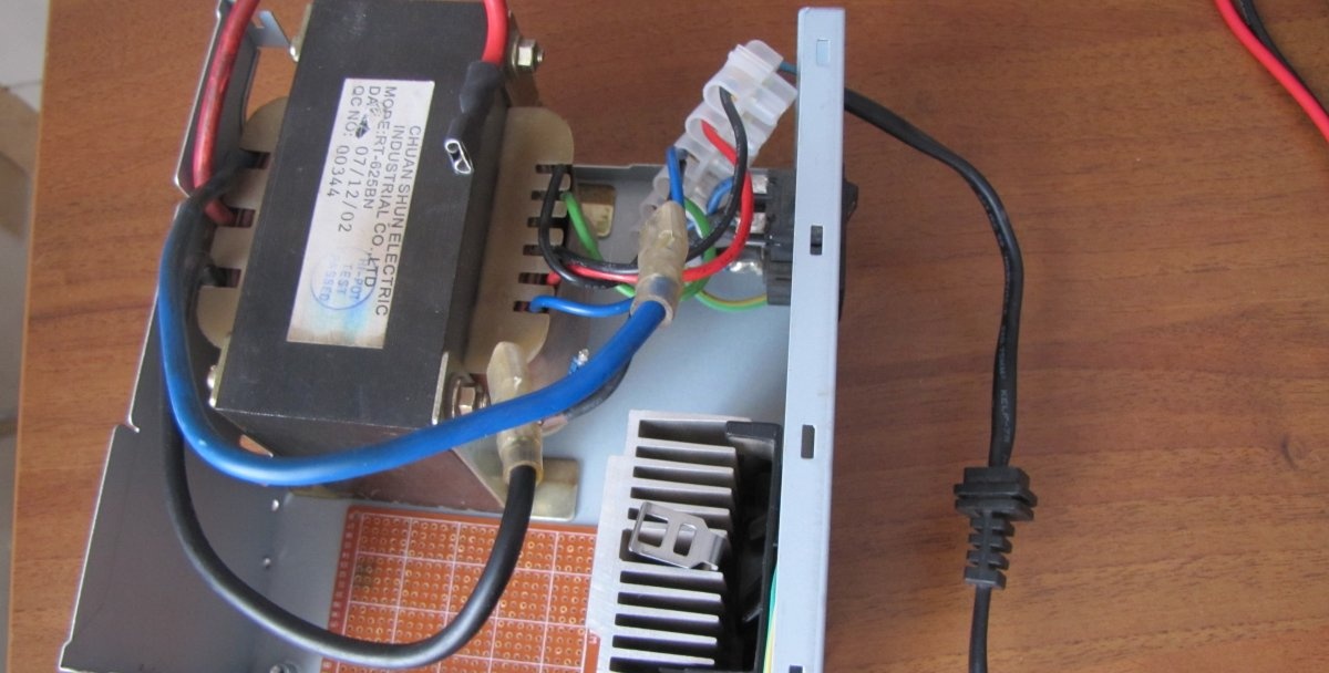
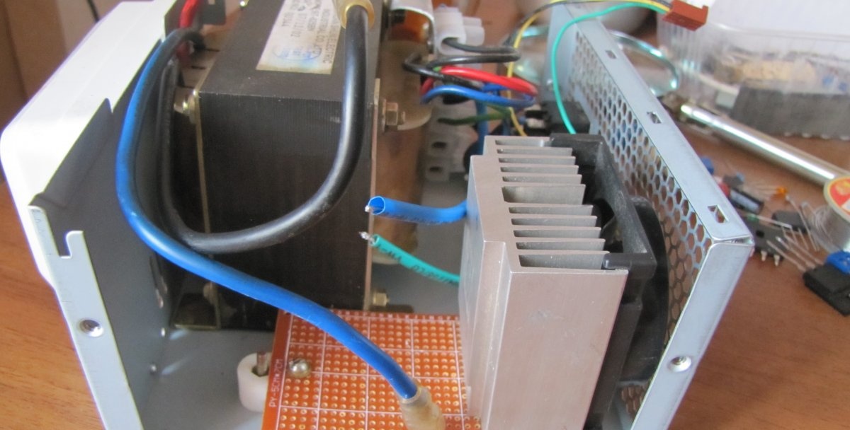
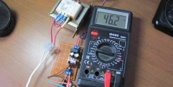
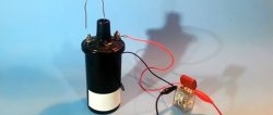
Let’s take the principle of auto-transformation from LATR and apply it to a conventional transformer, thereby increasing the voltage above the network voltage. I liked the transformer from the uninterruptible power supply. Mainly because it doesn't need to be rewound. It has everything you need. Transformer brand: RT-625BN.
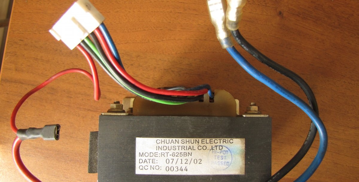

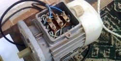
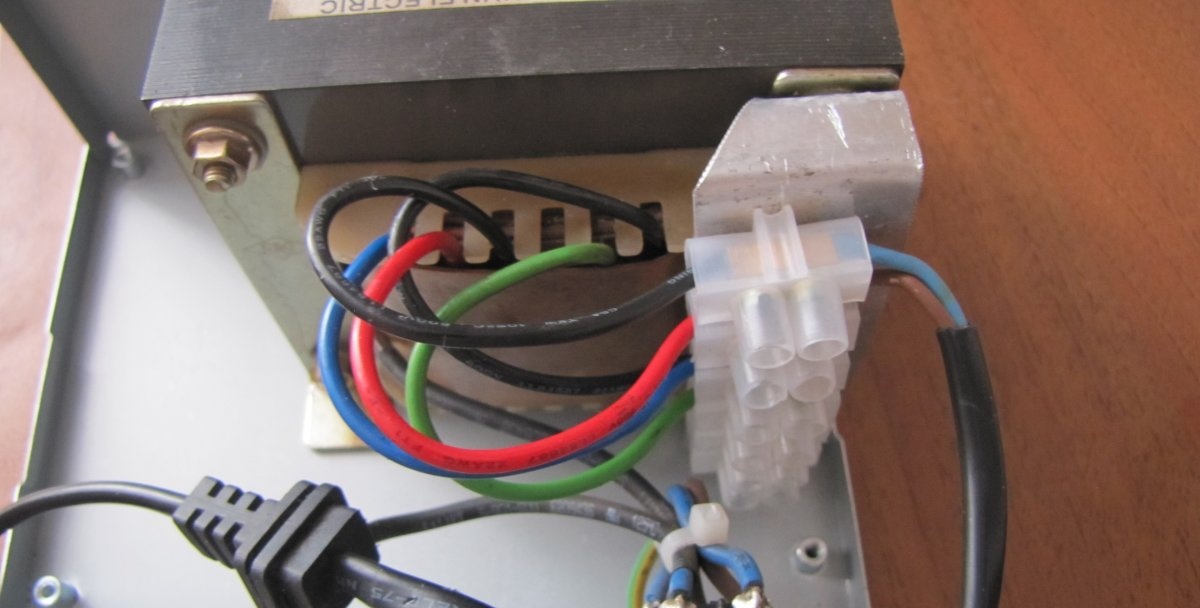
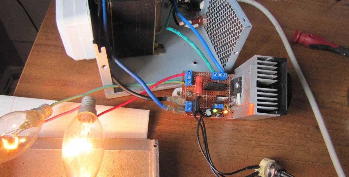
As can be seen from the diagram, in addition to the main winding of 220 volts, it contains two more, made with a winding wire of the same diameter, and two secondary powerful ones. The secondary windings are excellent for powering the control circuit and operating the cooler for cooling the power transistor. We connect two additional windings in series with the primary winding. The photographs show how this was done by color.
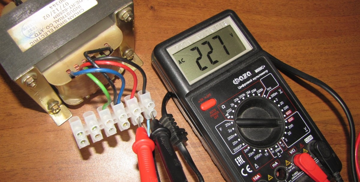
We supply power to the red and black wires.
Voltage is added from the first winding.
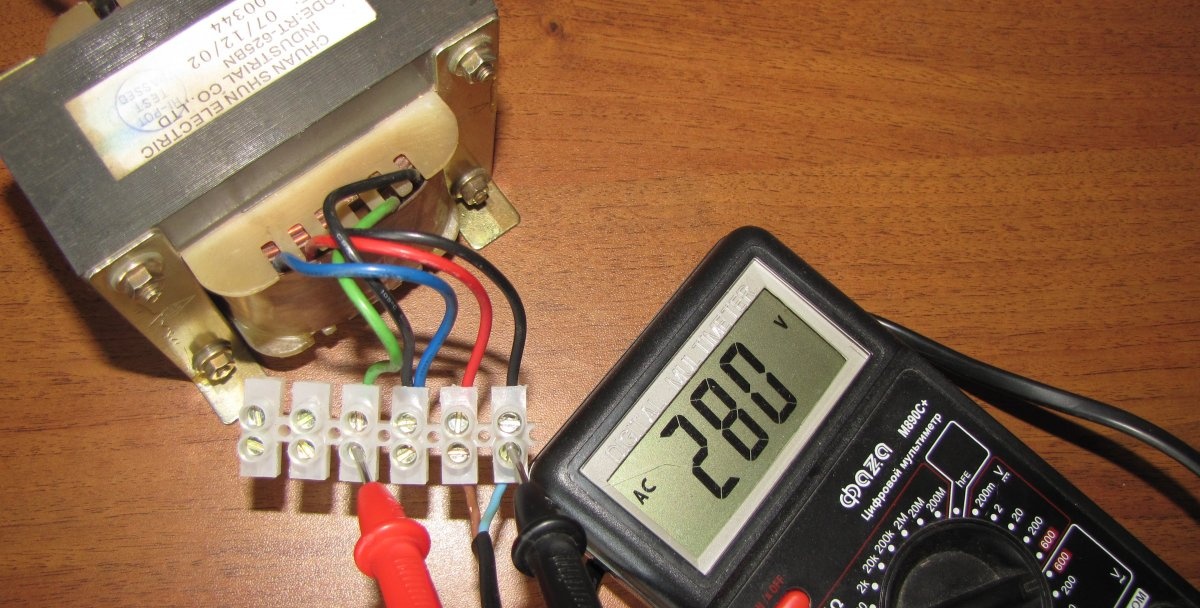
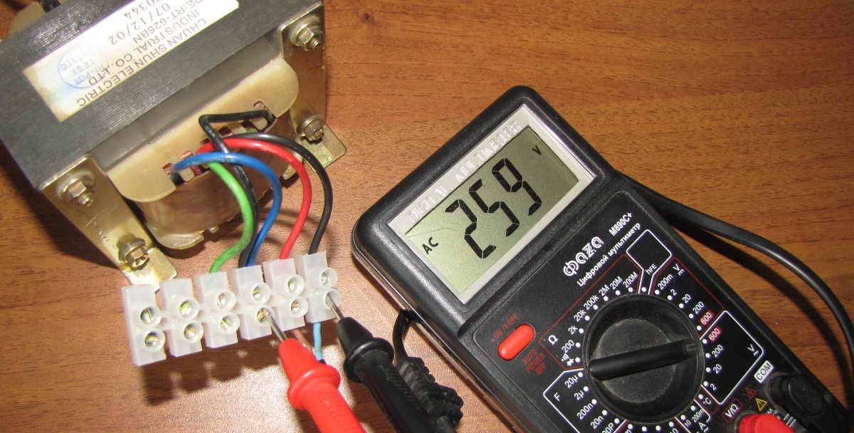
Plus two windings. The total is 280 volts.
If you need more voltage, you can wind more wires until the transformer window is filled, after first removing the secondary windings. Just be sure to wind it in the same direction as the previous winding, and connect the end of the previous winding to the beginning of the next one. The turns of the winding should, as it were, continue the previous winding.If you wind it in the opposite direction, it will be a big nuisance when you turn on the load!
You can increase the voltage, as long as the regulating transistor can withstand this voltage. Transistors from imported TVs are found up to 1500 volts, so there is room.
You can take any other transformer that suits your power, remove the secondary windings and wind the wire to the voltage you need. In this case, the control voltage can be obtained from an additional auxiliary low-power transformer of 8 - 12 volts.
If someone wants to increase the efficiency of the regulator, then they can find a way out here. The transistor wastes electricity on heating when it has to greatly reduce the voltage. The more you need to reduce the voltage, the stronger the heating. When open, the heating is negligible.
If you change the circuit of the autotransformer and make on it many outputs of the voltage levels you need, then by switching the windings you can supply the transistor with a voltage close to the one you need at the moment. There are no restrictions on the number of transformer pins; you only need a switch corresponding to the number of pins.
In this case, the transistor will be needed only for minor accurate voltage adjustments and the efficiency of the regulator will increase and the heating of the transistor will decrease.
Production of LATR
You can begin assembling the regulator.
I modified the diagram from the magazine a little, and this is what happened:
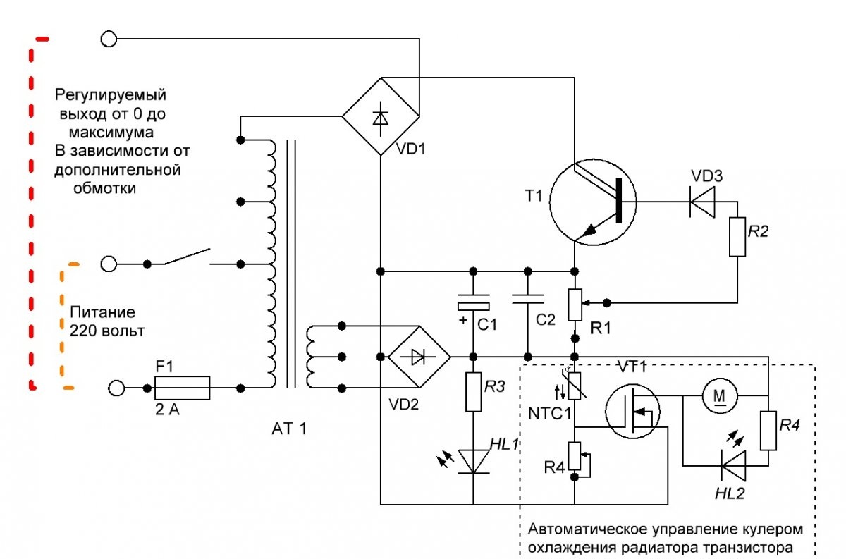
With such a circuit, you can significantly increase the upper voltage threshold. With the addition of an automatic cooler, the risk of overheating of the control transistor has been reduced.
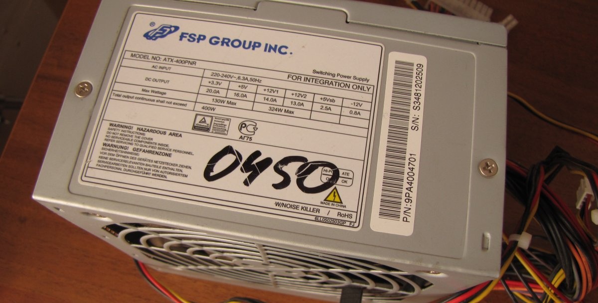
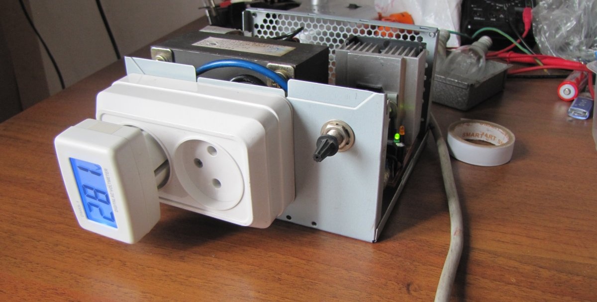
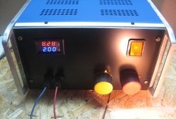
The case can be taken from an old computer power supply.
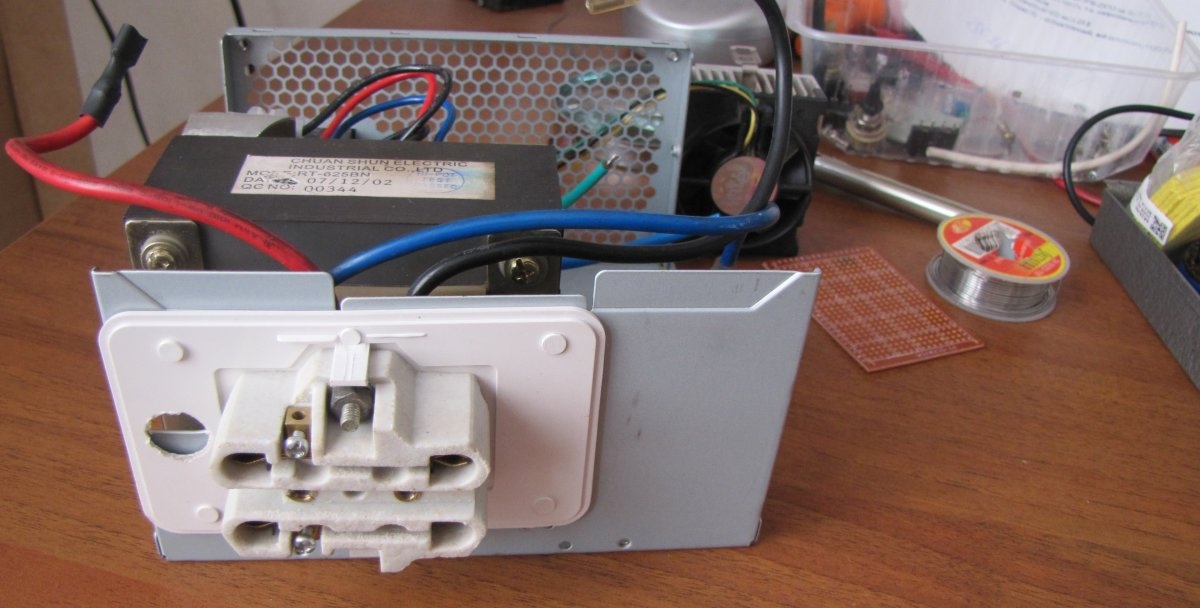
You immediately need to figure out the order of placement of the device blocks inside the case and provide for the possibility of their secure fastening.
If there is no fuse, then it is imperative to provide other short circuit protection.
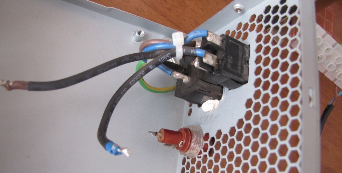
The high-voltage terminal block is securely attached to the transformer.
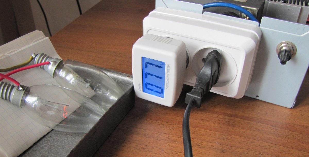
I installed a socket at the output to connect the load and control the voltage. The voltmeter can be set to any other voltage, but not less than 300 Volts.
Will need
We will need details:
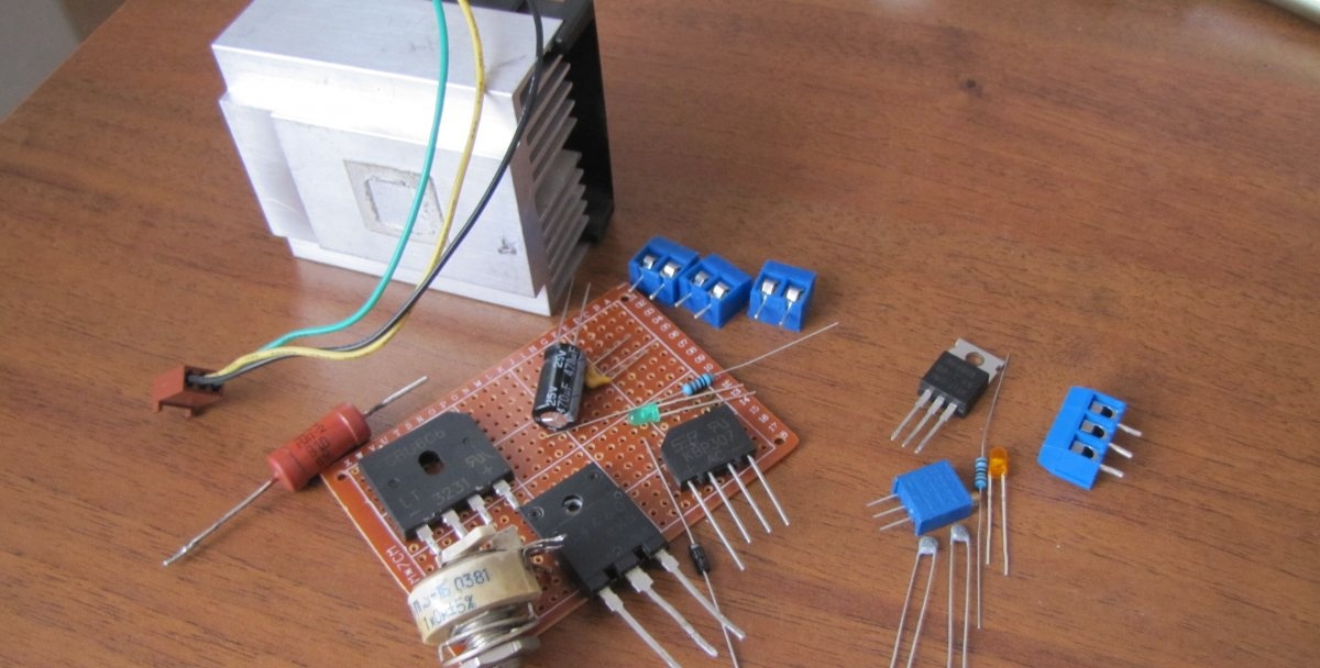
- Cooling radiator with cooler (any).
- Bread board.
- Contact blocks.
- Parts can be selected based on availability and compliance with nominal parameters; I used what came to hand first, but chose more or less suitable ones.
- Diode bridges VD1 - 4 - 6A - 600 V. From the TV, it seems. Or assemble it from four separate diodes.
- VD2 - for 2 - 3 A - 700 V.
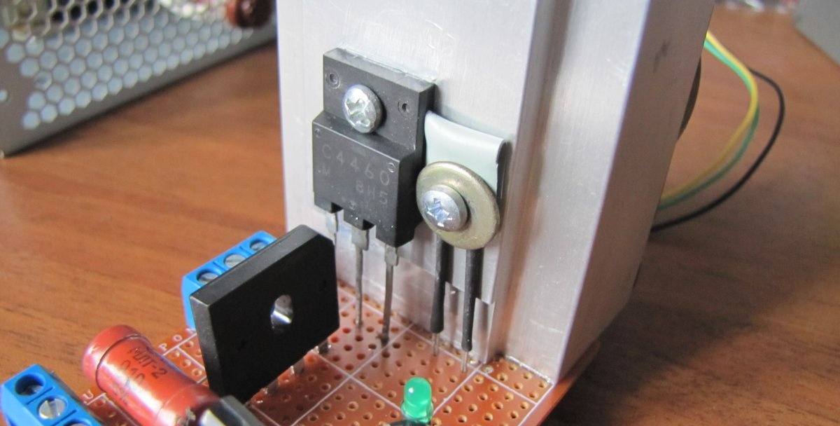
- T1 – C4460. I installed the transistor from an imported TV at 500V and a dissipation power of 55W. You can try any other similar high-voltage, powerful one.
- VD3 – diode 1N4007 1A 1000 V.
- C1 – 470mf x 25 V, it is better to increase the capacity even more.
- C2 – 100n.
- R1 – 1 kOhm potentiometer, any wirewound, from 500 Ohms and above.
- R2 – 910 - 2 W. Selection of transistor base current.
- R3 and R4 - 1 kOhm each.
- R5 – 5 kOhm substring resistor.
- NTC1 is a 10 kOhm thermistor.
- VT1 – any field-effect transistor. I installed RFP50N06.
- M – 12 V cooler.
- HL1 and HL2 – any signal LEDs, they do not need to be installed together with quenching resistors at all.
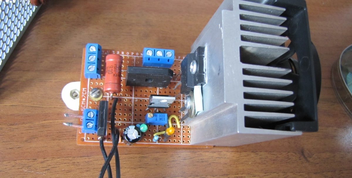
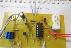
The first step is to prepare the board to house the circuit parts and secure it in place in the case.

We place the parts on the board and solder them.


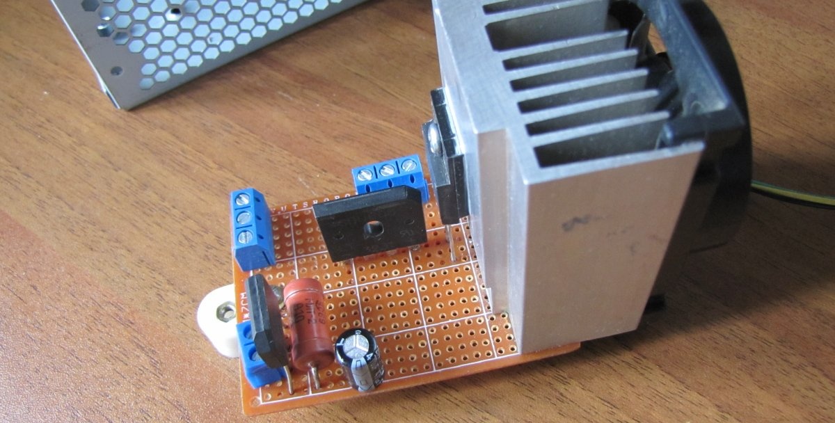
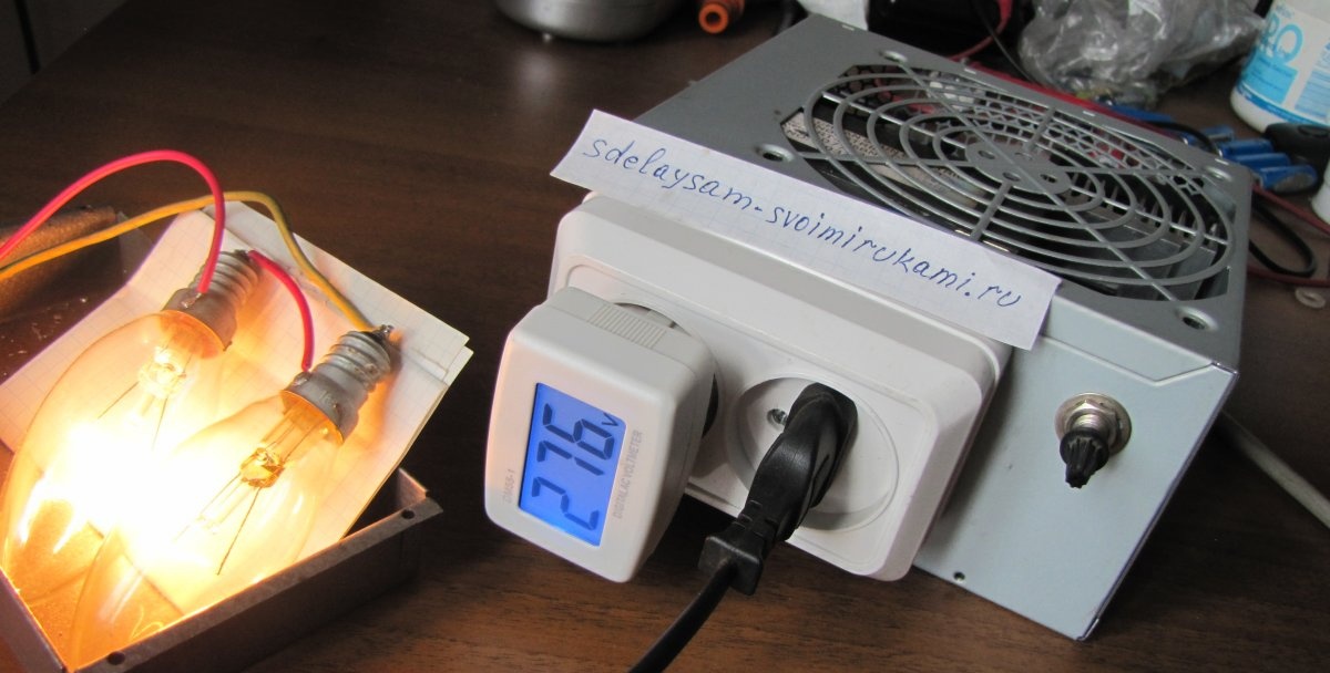
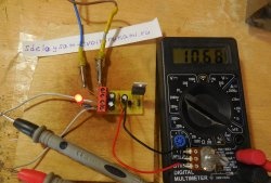
When the circuit is assembled, it is time for its preliminary testing. But this must be done very carefully. All parts are under mains voltage.
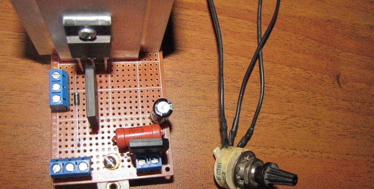
To test the device, I soldered two 220 volt light bulbs in series so that they would not burn out when 280 volts were applied to them. There were no bulbs of the same power and therefore the filament of the spirals varied greatly. It must be borne in mind that without a load the regulator operates very incorrectly. The load in this device is part of the circuit. When you turn it on for the first time, it’s better to take care of your eyes (in case you messed something up).
Turn on the voltage and use a potentiometer to check the smoothness of the voltage adjustment, but not for long, to avoid overheating of the transistor.

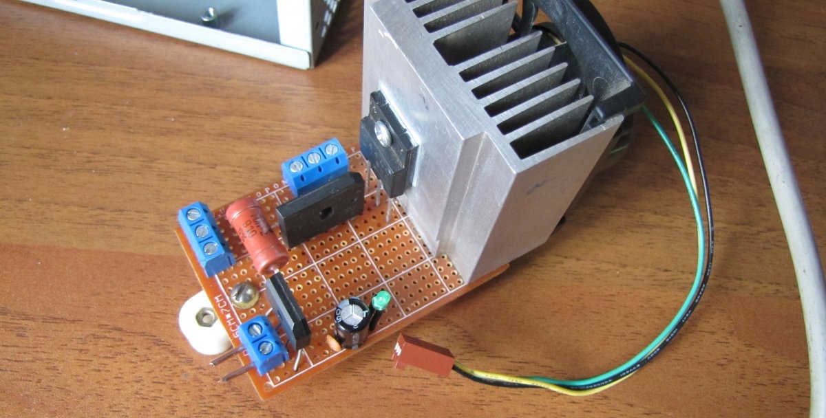
After the tests, we begin to assemble a circuit for automatic operation of the cooler, depending on the temperature.
I didn’t have a 10 kOhm thermistor, so I had to take two 22 kOhm ones and connect them in parallel. It turned out to be about ten kOhms.
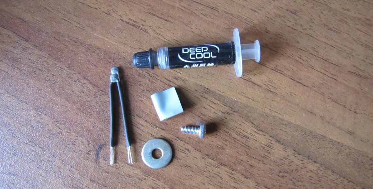
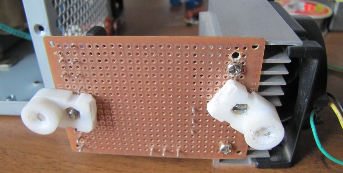
We attach the thermistor next to the transistor using thermal conductive paste, as for the transistor.
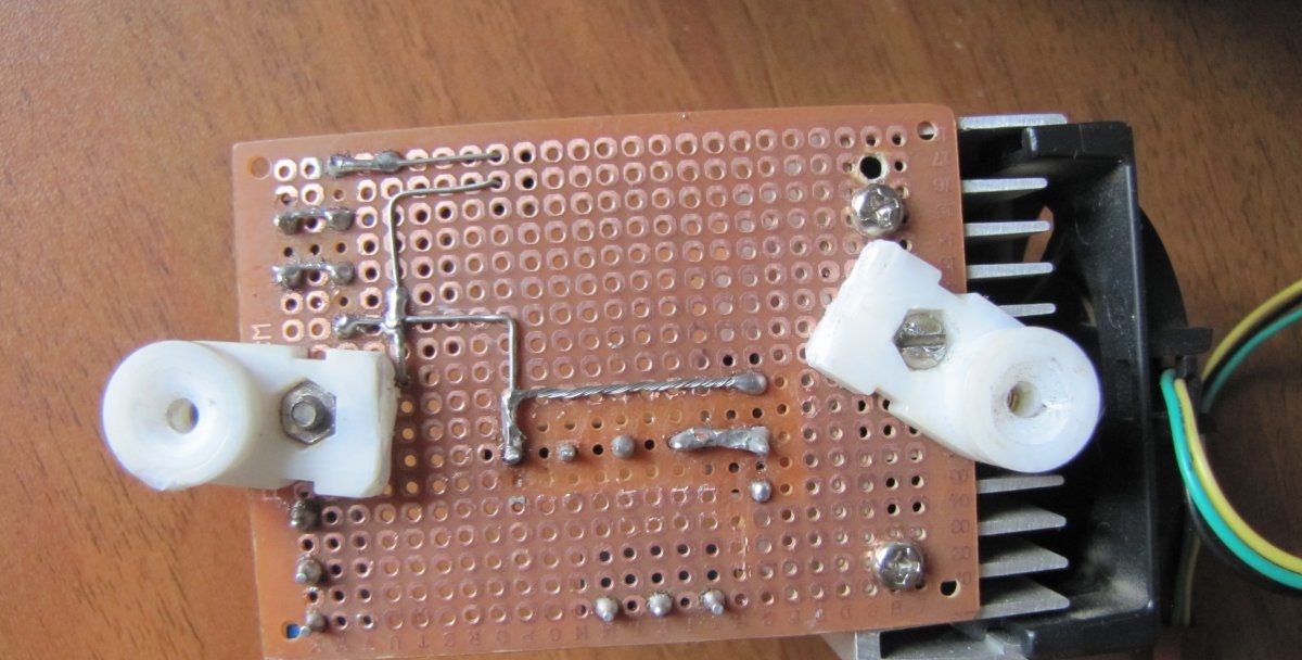
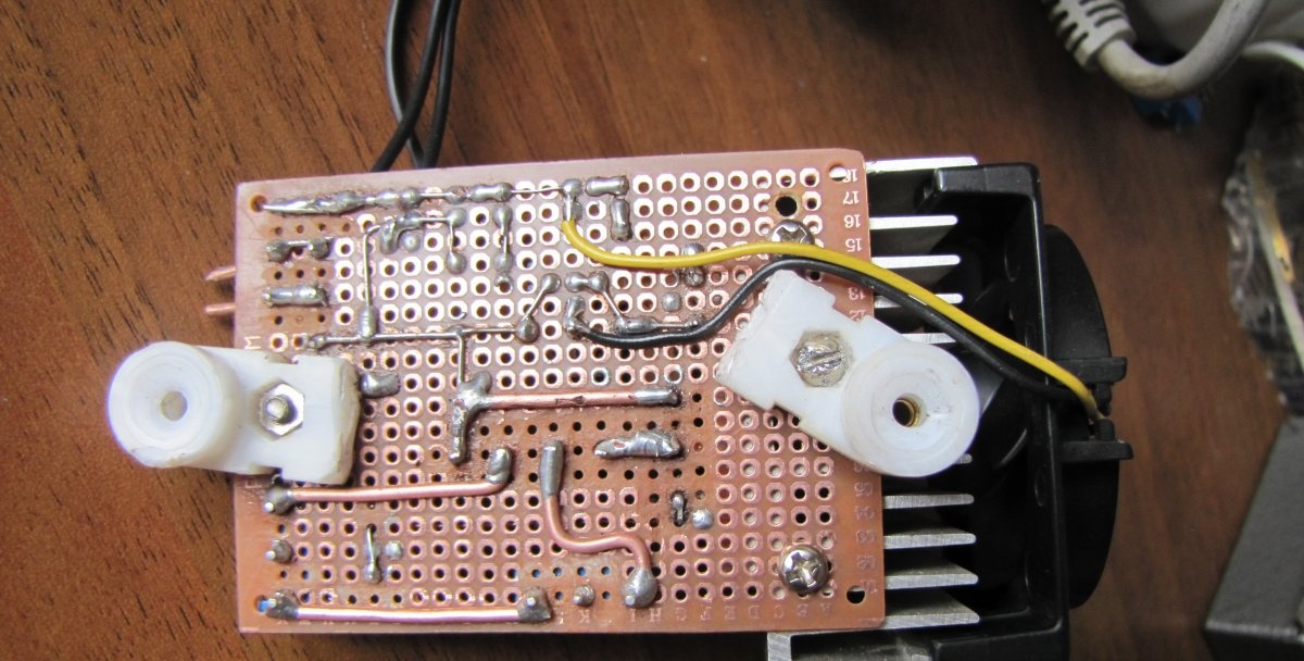
We install the remaining parts and solder them. Do not forget to remove the copper contact pads of the breadboard between the conductors, as in the photo, otherwise a short circuit may occur in these places when the high voltage is turned on.
All that remains is to adjust the start of operation of the cooler when the radiator temperature increases using a trimmer resistor.
We place everything in the body in its regular places and secure it. We finally check and close the lid.
Please watch the video of the noise-free voltage regulator in operation.
Good luck to you.
Watch the video
Similar master classes
Particularly interesting