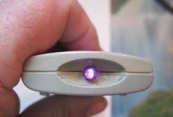
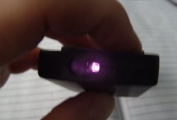
As is known, in addition to the visible light spectrum, there is also infrared radiation, which is not perceived by the human eye. It is often used in remote controls to transmit various commands. An interesting fact - to “see” infrared light, just point the lens of a digital camera at the IR emitter of the remote control and press the keys on it. A luminous dot will be visible on the camera screen - this is infrared Light-emitting diode.
IR rays in radio electronics make it possible to create an interesting device called an infrared barrier. It consists of two parts - a transmitter and a receiver. The transmitter is a regular IRLight-emitting diode, which receives bursts of pulses. The receiver continuously catches and detects these bursts of pulses. When there is a free visible connection between the receiver and the transmitter, i.e. the light “reaches” freely to the receiver, and a logical zero is set at the output. But as soon as a foreign object appears in the coverage area, the connection is instantly disrupted and the receiver signals this.Such a barrier can be used, first of all, in security alarms, because IR radiation cannot be seen with the naked eye.
The advantage of this particular scheme is that the infrared Light-emitting diode It glows not continuously, but pulsed. Firstly, this extends the life of the LED itself and reduces current consumption, and secondly, it is a good means of protection against false alarms, so the circuit can be safely used even outdoors when the receiver is exposed to direct sunlight.
Transmitter circuit
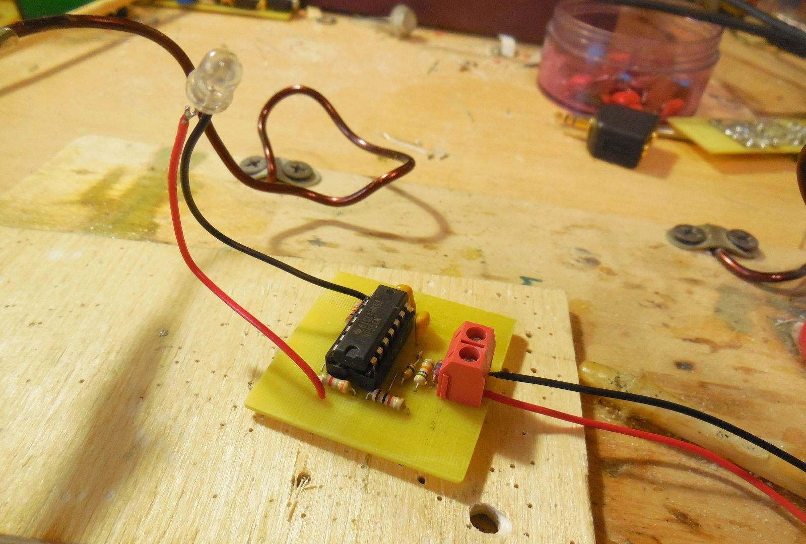
The transmitter circuit is based on a dual integrated timer NE556, which generates pulses for the emitting LED LED1, resistor R2 sets the radiation power. All other elements of the circuit must strictly comply with the specified rating in order to maintain the desired frequency of the generator. D1 – any low-power diode, for example, 1N4148, 1N4007, KD521.
Receiver circuit
The key element of the circuit is a special IR signal receiver, designated TSOP (Temic Semiconductors Opto Electronics Photo Modules). You can find it on any TV that has a remote control. Any receiver designed for a frequency of 36 kHz, for example, TSOP1736, is suitable here. This receiver controls the gate of field-effect transistor VT1. Because the signal from the receiver output is about 5 volts, then the transistor must be used with logical control, for example, IRL520 or any others from the IRL series. As a last resort, you can install a regular field one, for example, IRF540, IRF740, IRF630, but it will not open completely. Light-emitting diode LED1 indicates the output status of the circuit.When the visible connection between the receiver and the transmitter is not broken, the output voltage is zero, LED1 is not lit. As soon as a foreign object appears in the coverage area, LED1 lights up and the voltage at the OUT output becomes equal to the supply voltage. D1 in the diagram is a 5 volt zener diode, you can use, for example, 1N4733.
You can download the board here:
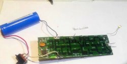
IR barrier assembly
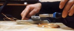
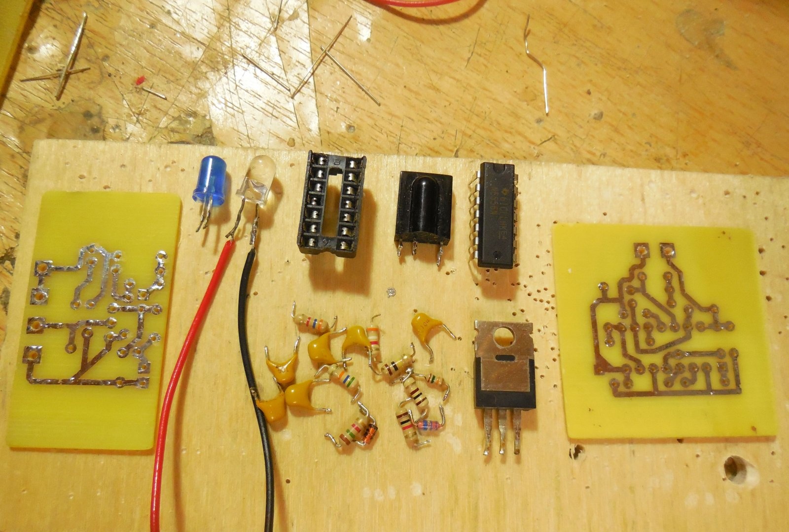
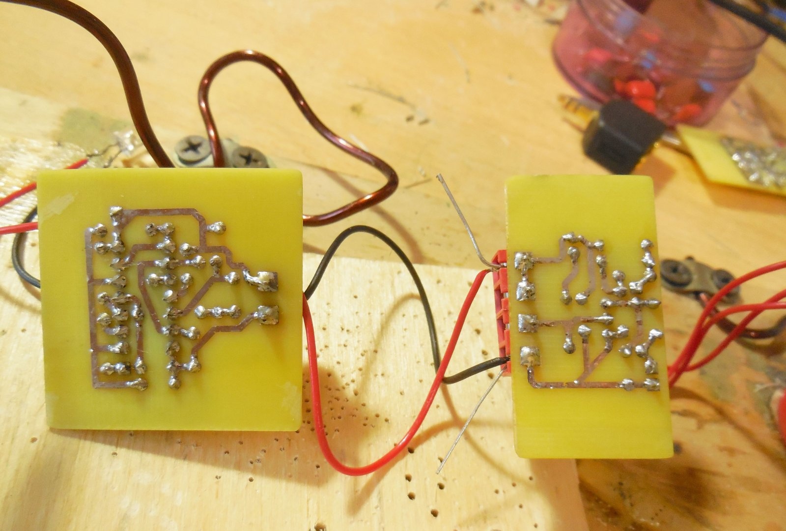
Each circuit is assembled on its own printed circuit board, the TSOP receiver and IR LED are output on wires. The boards are made using the LUT method, below are a couple of photographs of the process: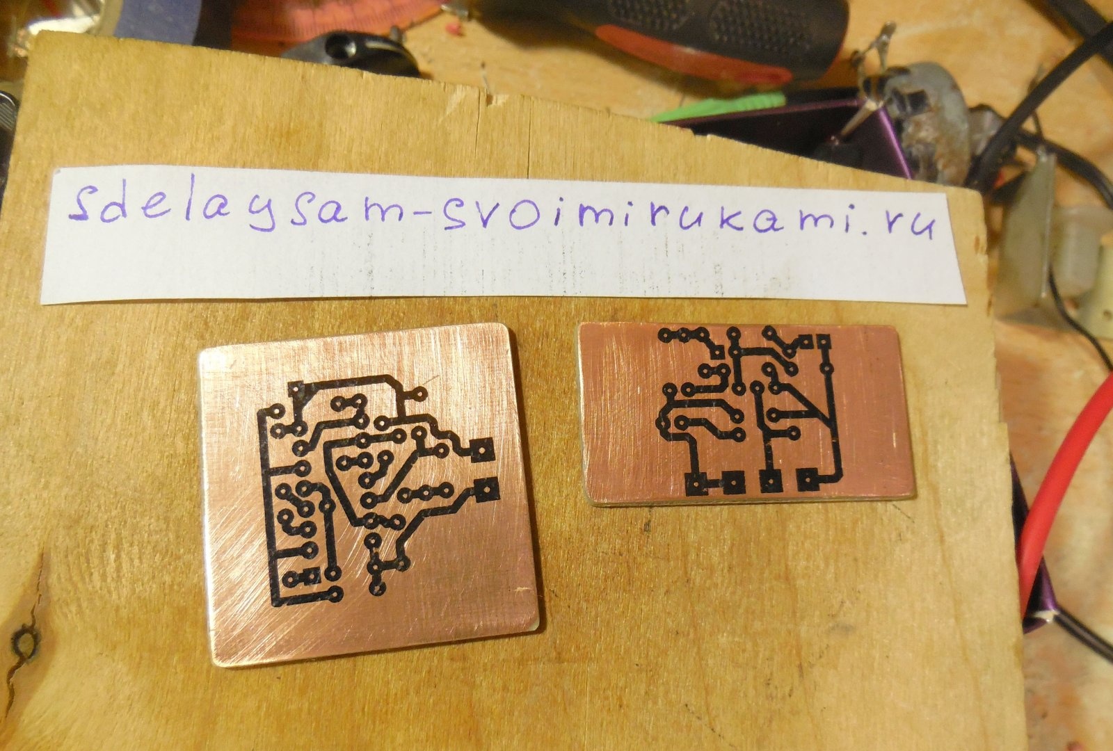
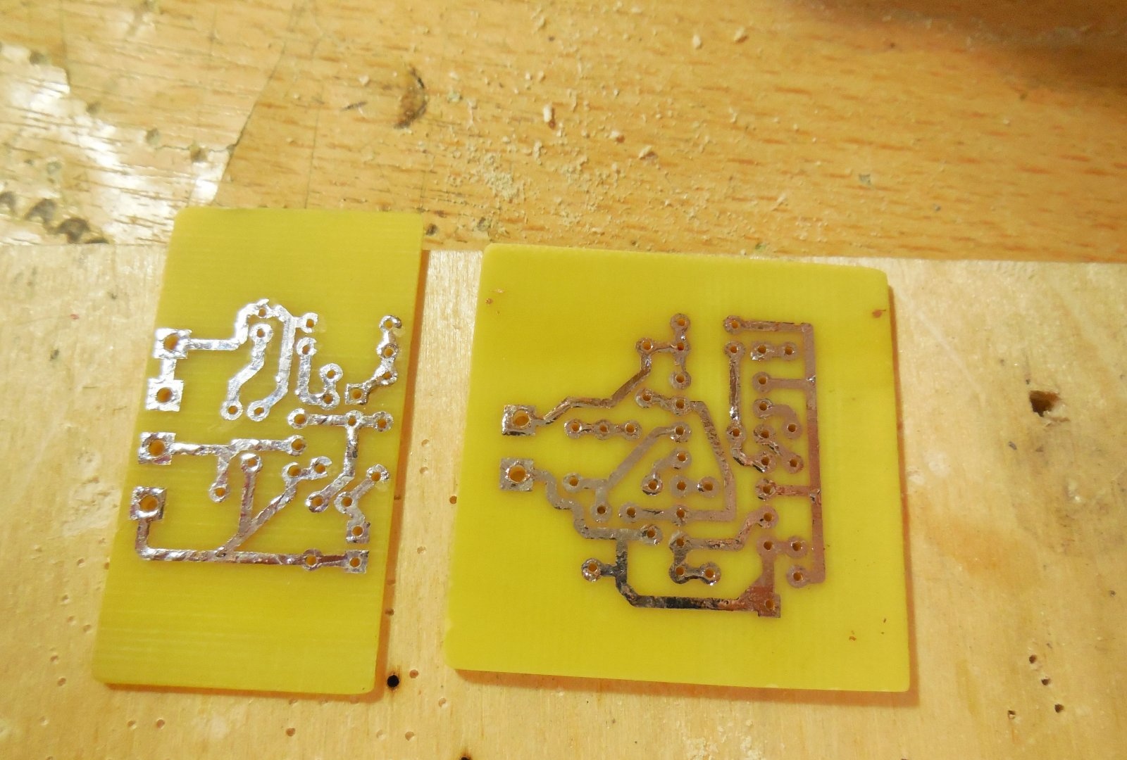
As when creating any electronic device, first small parts - resistors, diodes - are soldered onto the board. Then the capacitors, and after them everything else. It is advisable to install the microcircuit in the socket, and connect the power wires through terminal blocks for convenience. After soldering, wash off any remaining flux from the board and test the tracks for short circuits.
Setup and testing
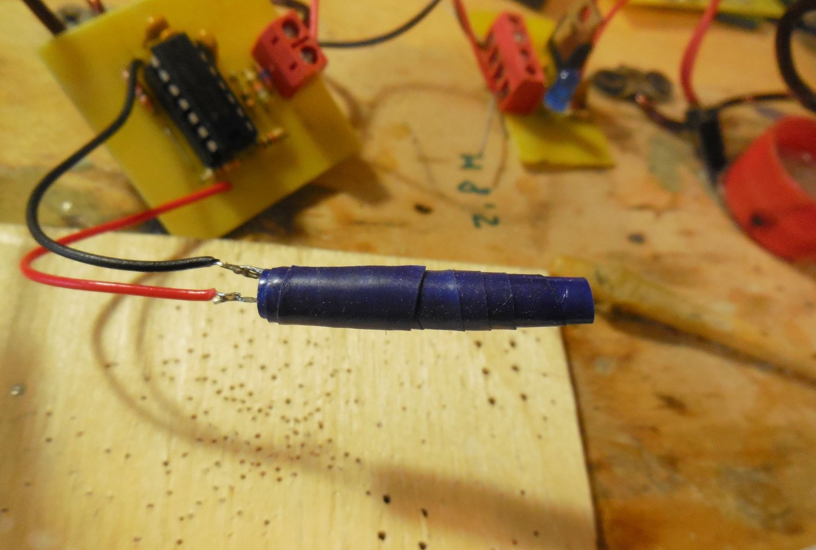
After assembly, you can supply power to the boards. The supply voltage for both circuits is 9-12 volts. After turning it on, you need to make sure that the voltage at the cathode of the zener diode in the receiver circuit is approximately 5 volts. If it is higher, you need to check the functionality of the zener diode and resistor R2, otherwise the TSOP receiver may burn out. After starting the transmitter, you can look at the LED through the camera lens; it should glow slightly. It is advisable to place the LED in a tube 3-4 centimeters long so that the light does not scatter to the sides, but is directed strictly in one direction.
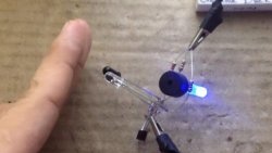
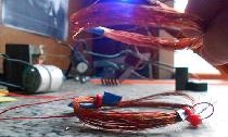
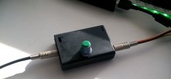
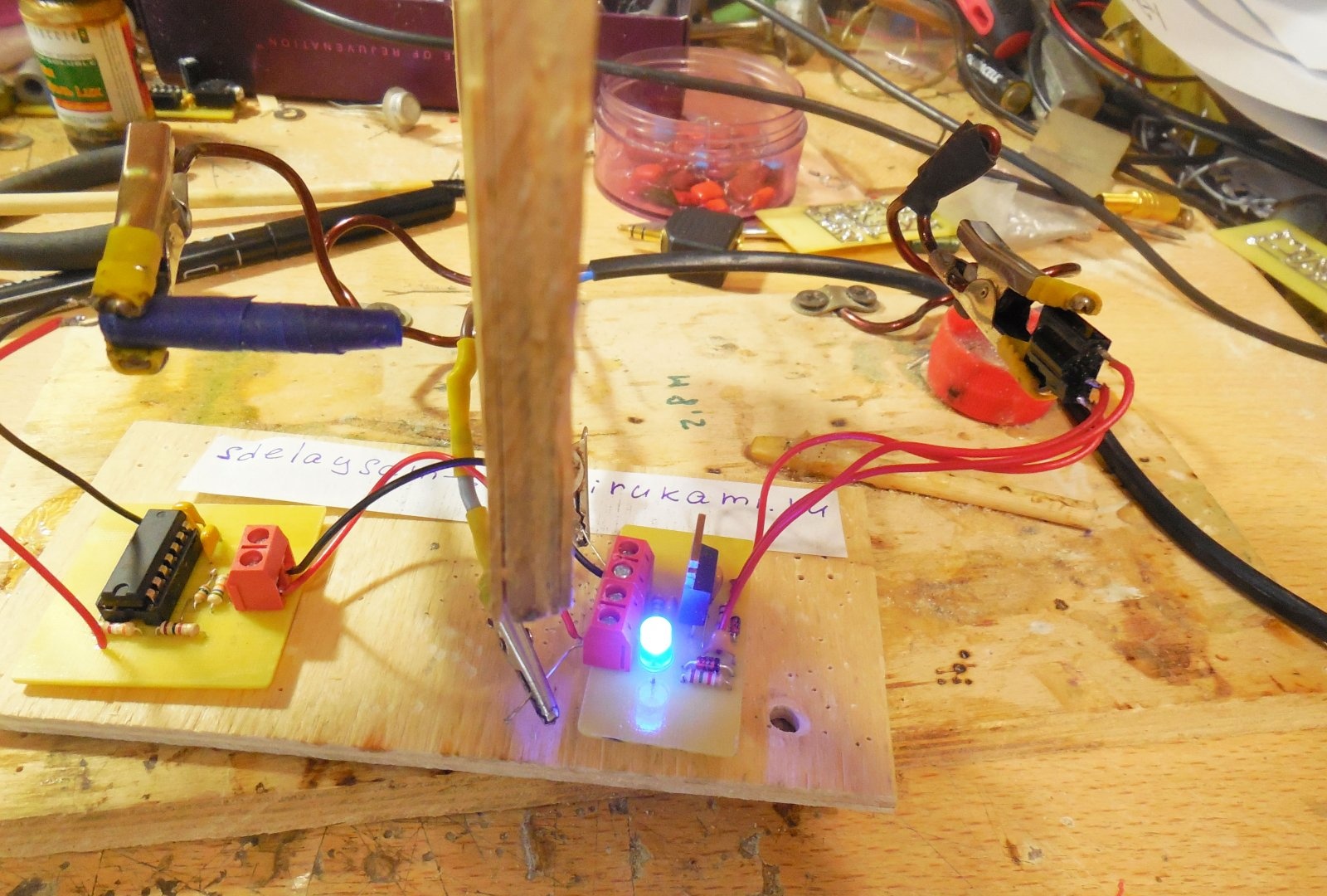
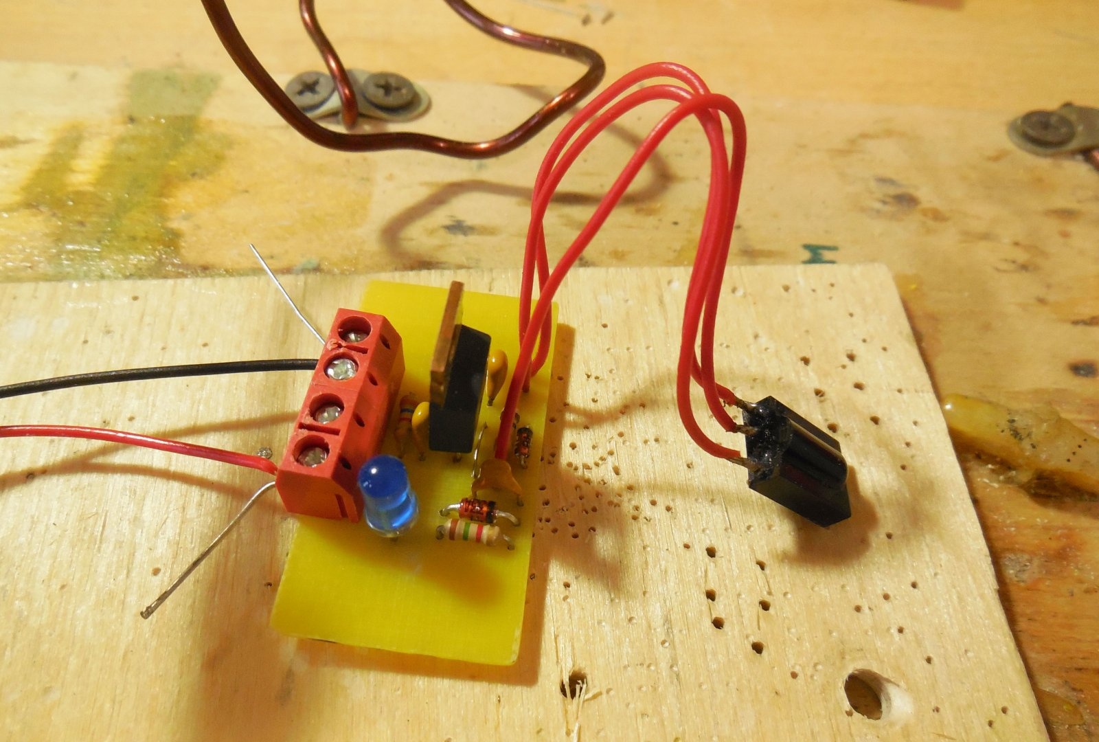
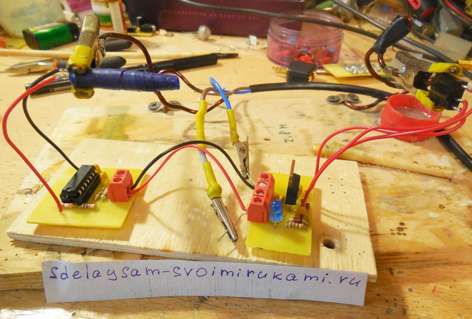
Now you can point the LED tube at the receiver and see what happens.When there is a visible connection between them, the blue LED is off, this can be seen in the photo.
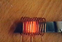
Now we place a piece of plywood in the path of the IR radiation flow, the connection between the receiver and the transmitter will be lost and the blue LED will immediately light up.
You can experiment with different materials. Paper and transparent plastic transmit infrared radiation, so the IR barrier does not react to them. But metal, wood, a human hand or other dense materials are an obstacle to the rays, as can be seen in the video.