Until now, some people use hourglass to count small periods of time. Watching the movement of grains of sand in such a watch is very exciting, but using them as a timer is not always convenient. Therefore, they are being replaced by an electronic timer, the circuit of which is presented below.
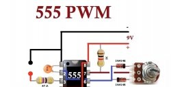
Timer circuit

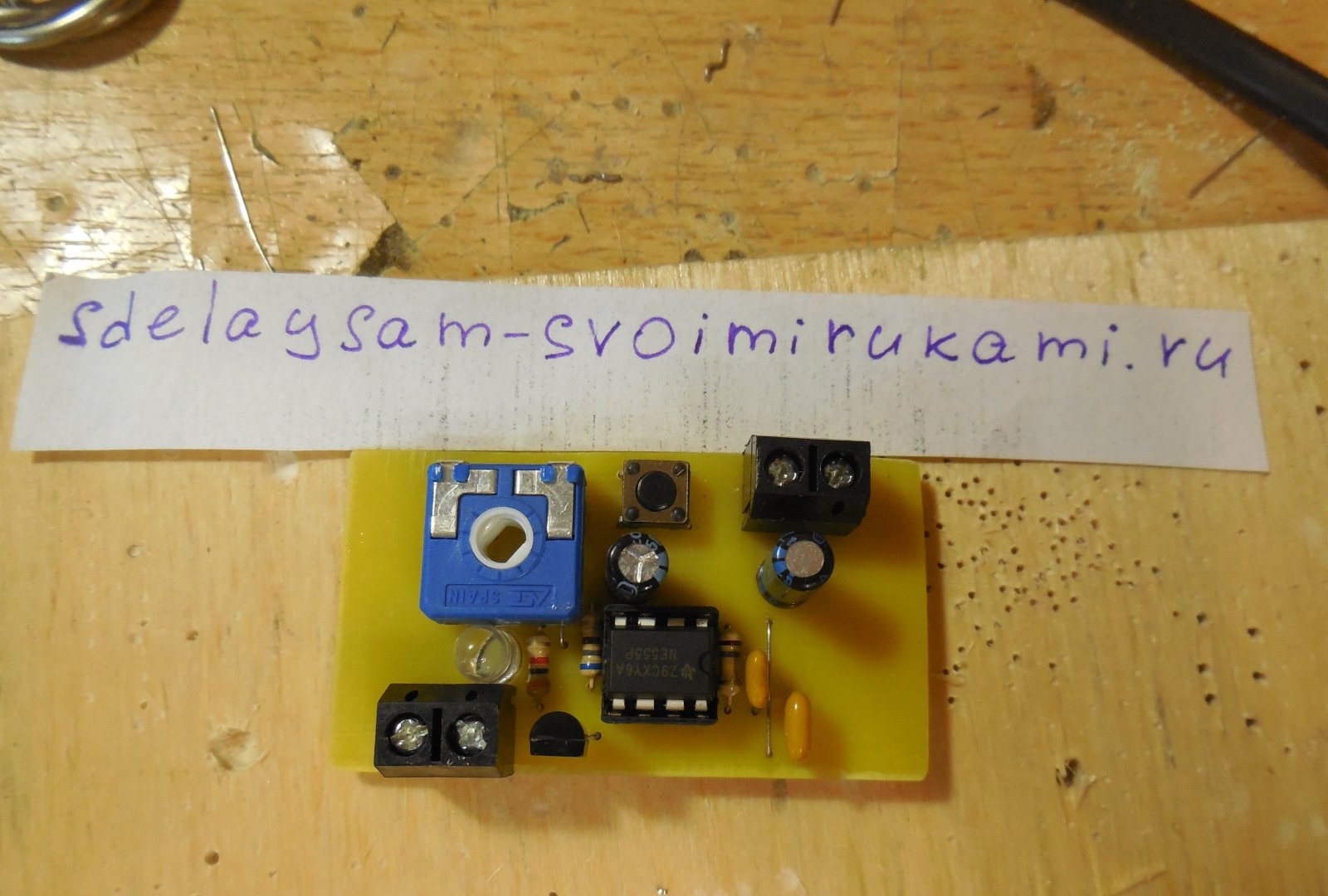
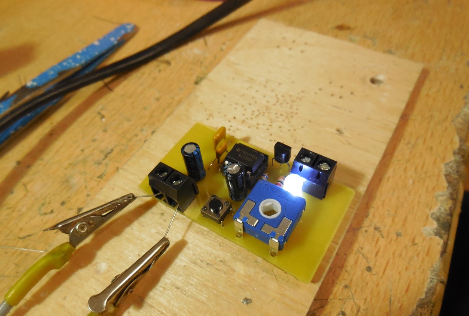
It is based on the widespread inexpensive chip NE555. The operation algorithm is as follows - when the S1 button is pressed briefly, the output voltage OUT appears equal to the supply voltage of the circuit and LED1 lights up. After a specified period of time, the LED goes out, the voltage at the output becomes equal to zero. The timer is set by the trimming resistor R1 and can vary from zero to 3-4 minutes. If there is a need to increase the maximum timer delay time, then you can raise the capacitance of capacitor C1 to 100 μF, then it will be approximately 10 minutes. As a transistor T1, you can use any bipolar transistor of medium or low power structure n-p-n, for example, BC547, KT315, BD139. As button S1, any button for closing without fixing is used. The circuit is powered by a voltage of 9 - 12 volts, the current consumption without load does not exceed 10 mA.
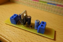
Making a timer
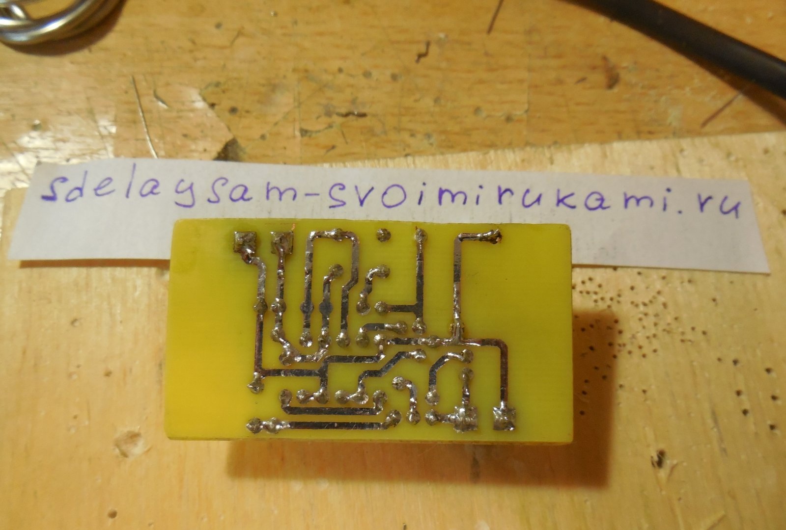
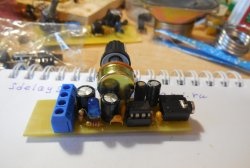
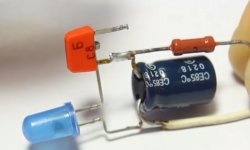
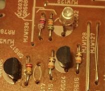
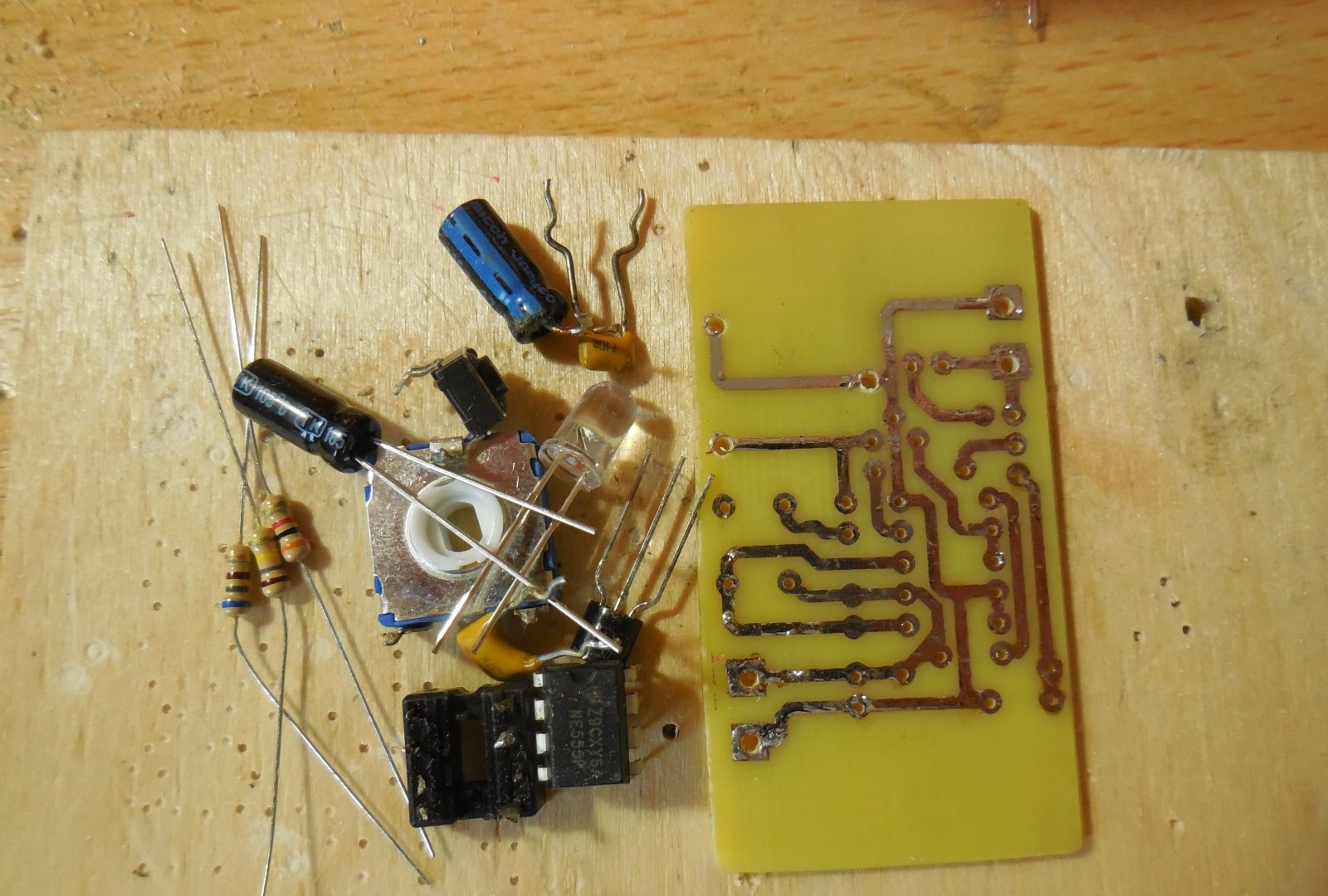
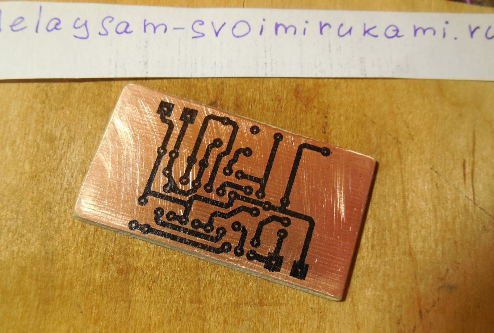
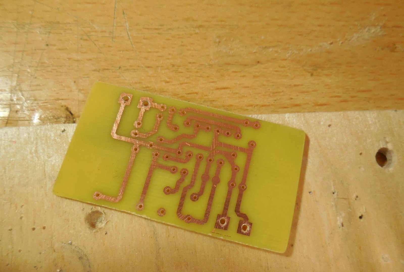
The circuit is assembled on a printed circuit board measuring 35x65, the file for the Sprint Layout program is attached to the article. The tuning resistor can be installed directly on the board, or can be output on the wires and use a potentiometer to adjust the operating time. To connect the power and load wires, there are places for screw terminal blocks on the board. The board is performed by the LUT method, several photos of the process:
Download board:
[2.75 Kb] (downloads: 201)
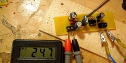
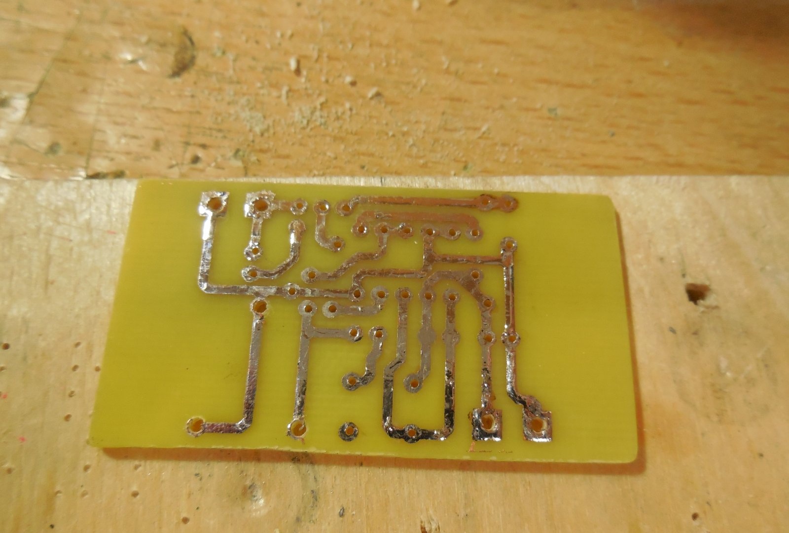
After soldering all the parts, the board must be washed away from the flux, the neighboring tracks should ring for a short circuit. The assembled timer does not need to be configured, it remains only to set the desired operating time and press the button. You can connect a relay to the OUT output, in which case the timer will be able to control a powerful load. When installing the relay parallel to its winding, a diode should be installed to protect the transistor. The scope of such a timer is very wide and is limited only by the user's imagination. Have a nice build!