When you collect some kind of electronic homemade product, then you need a power supply to check it. There is a wide variety of turnkey solutions on the market. Beautifully decorated, have many features. There are also many self-made kit kits. I'm not talking about the Chinese with their trading floors. I bought on Aliexpress the boards of the step-down converter modules, so I decided to do it on it. The voltage is adjustable, the current is enough. The block is based on a module from China, as well as the radio components that were in my workshop (they had been lying and waiting in the wings for a long time). Regulates the unit from 1.5 volts to a maximum (it all depends on the rectifier used to the adjustment board.
Component Description
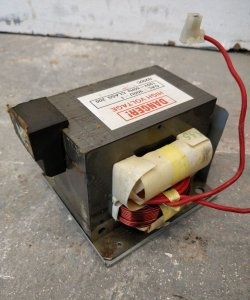
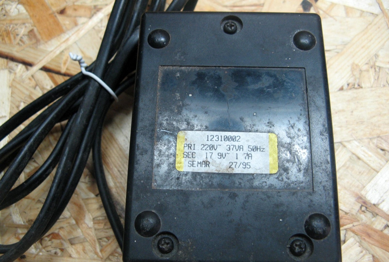
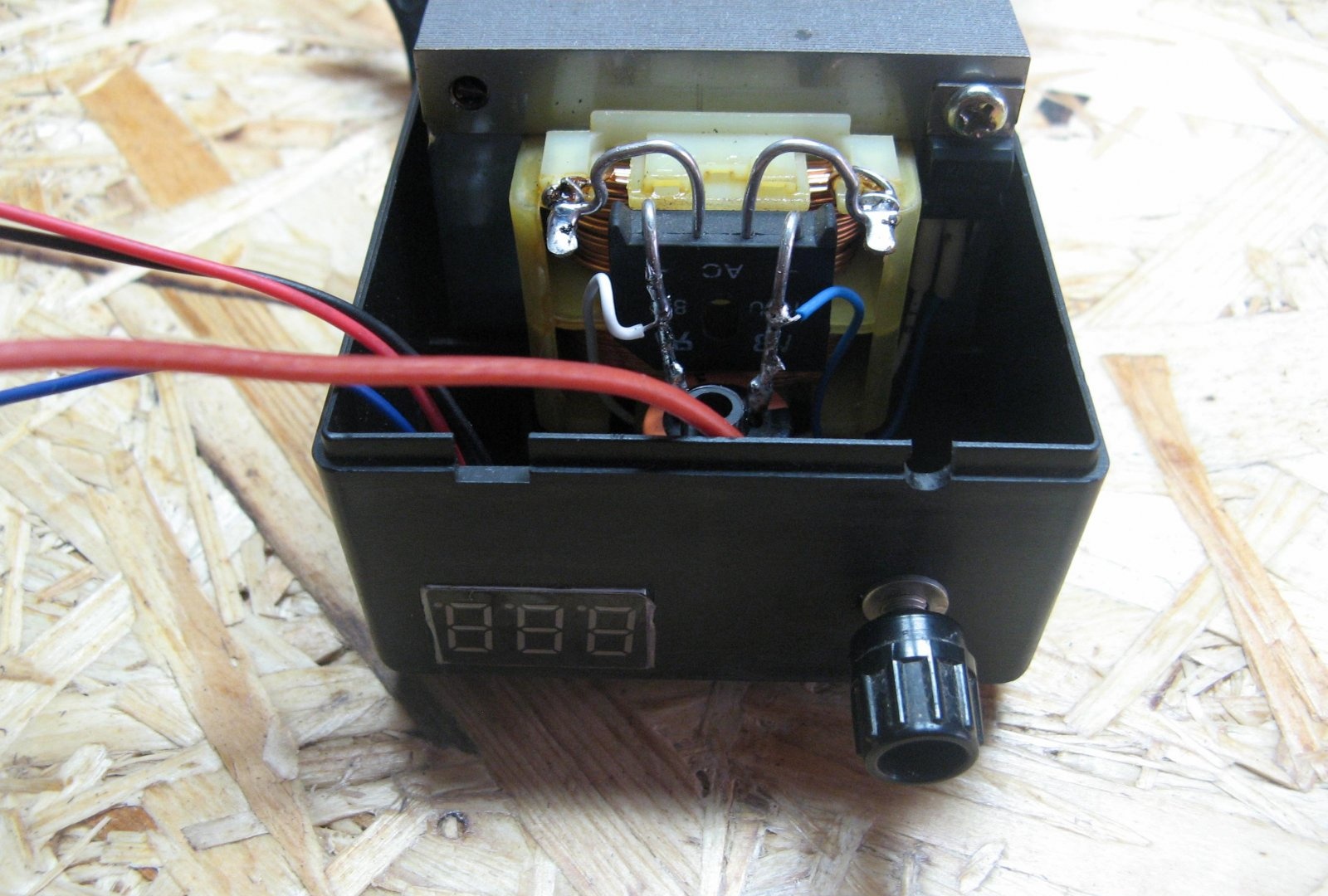
I have a transformer of 17.9 Volts and a current of 1.7 Amps. It is installed in the case, so you do not need to select the latter. The winding is quite thick, I think 2 amperes will pull. Instead of a transformer, you can use a switching power supply for the laptop, but then you also need a housing for the other components.
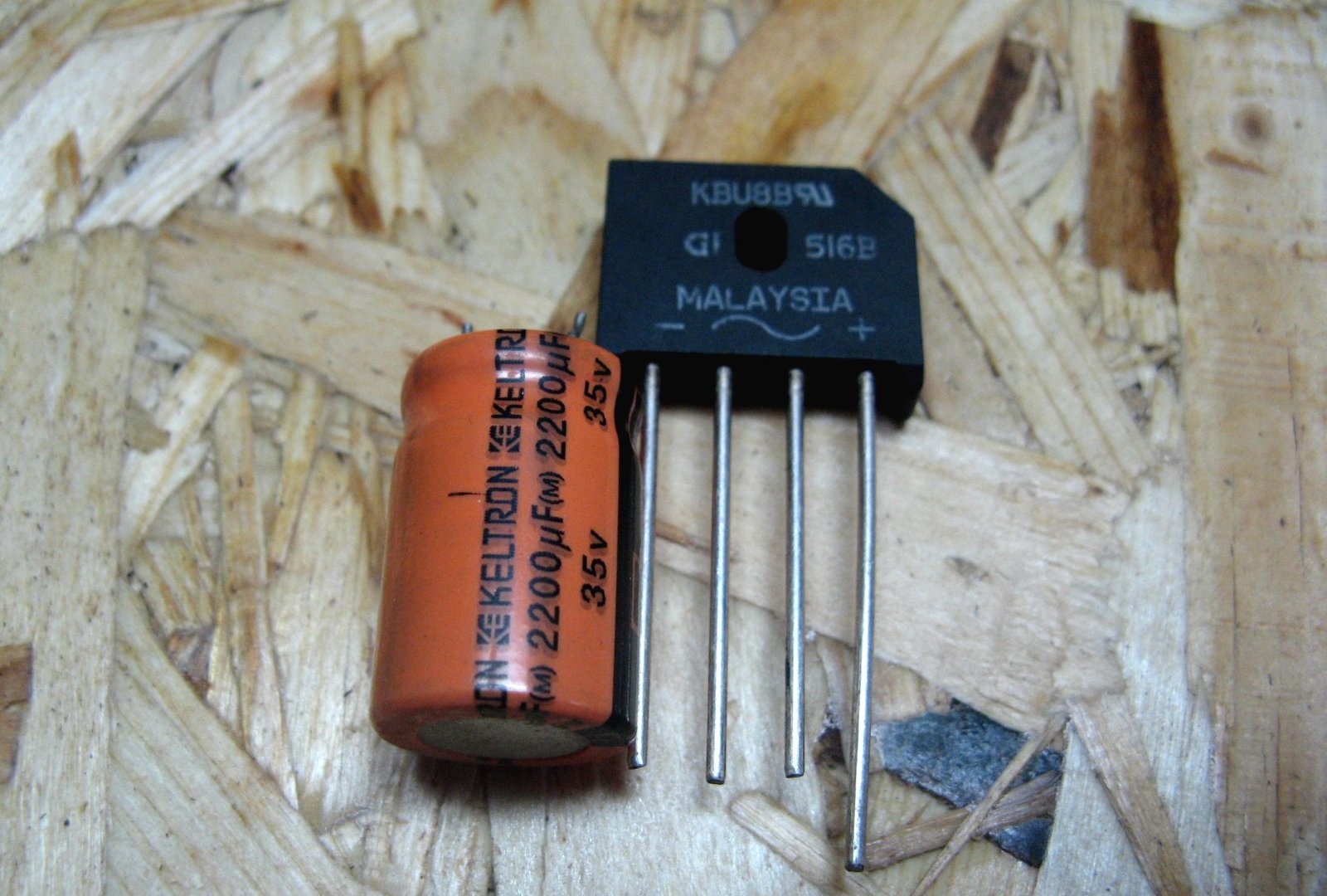
An AC rectifier, there will be a diode bridge, can be assembled from four diodes. The ripple will smooth out the electrolytic capacitor, I have 2200 microfarads and an operating voltage of 35 volts. Used b / y, was available.
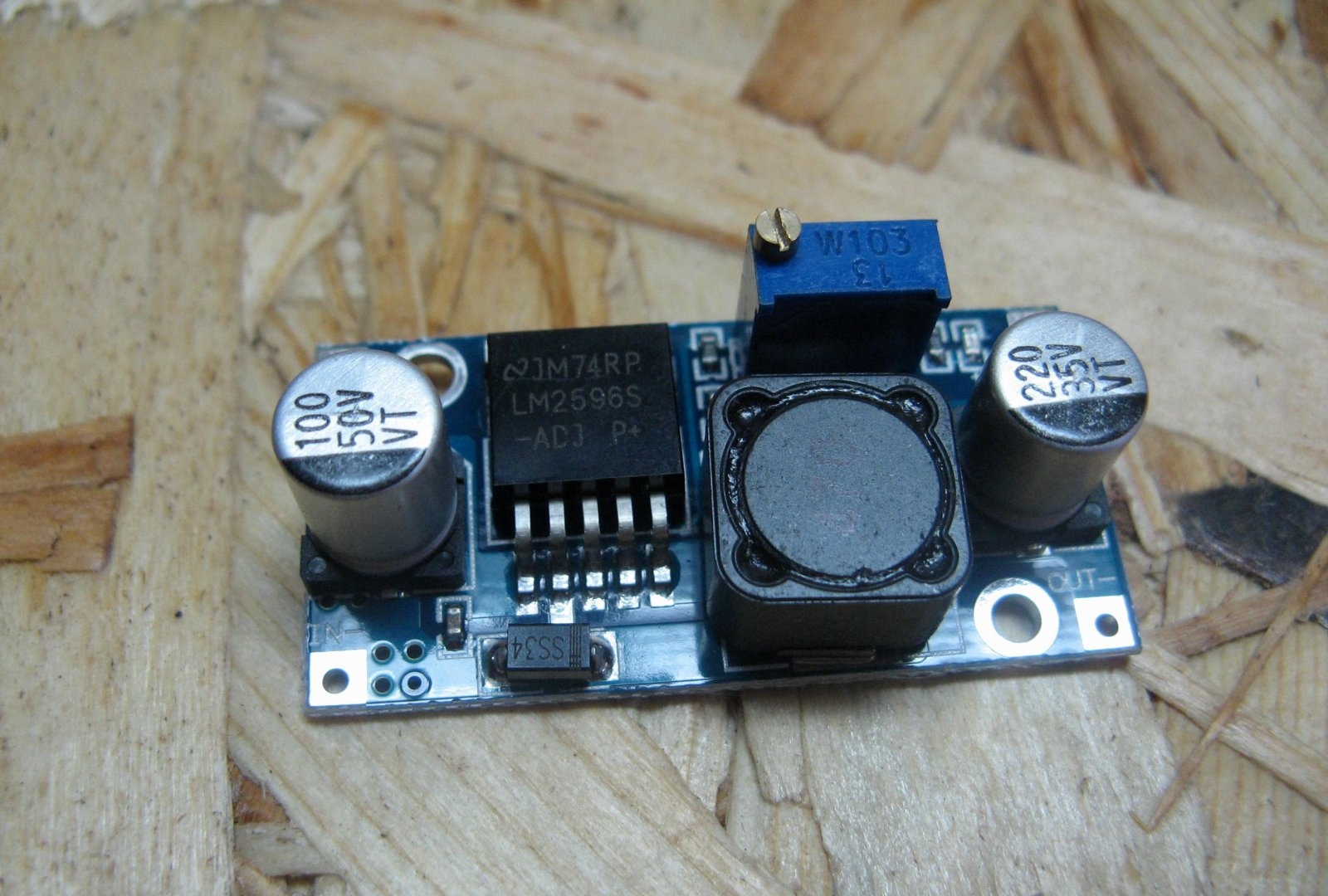
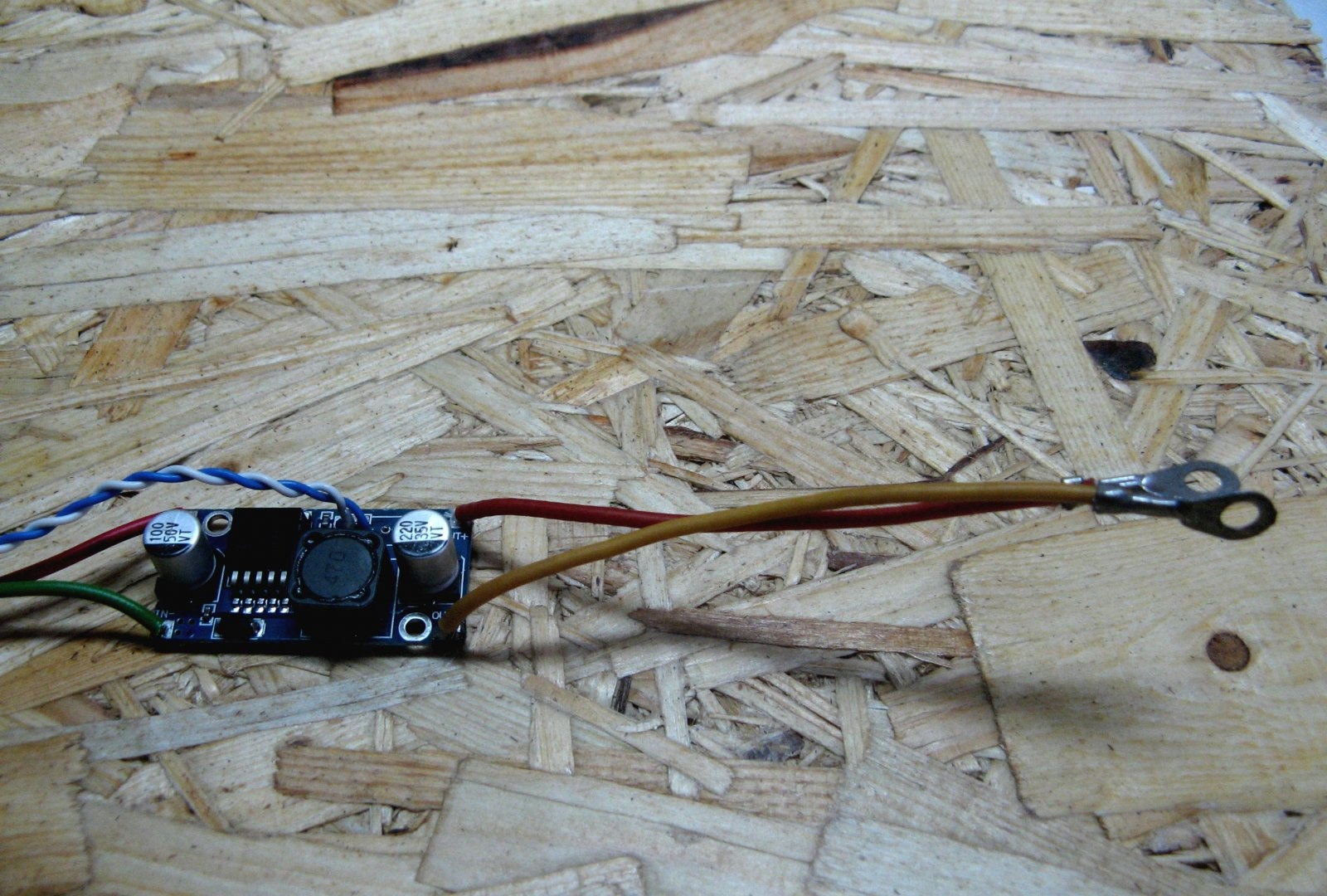
I will adjust the output voltage . There are a lot of them on the market. It provides good stabilization and is quite reliable.
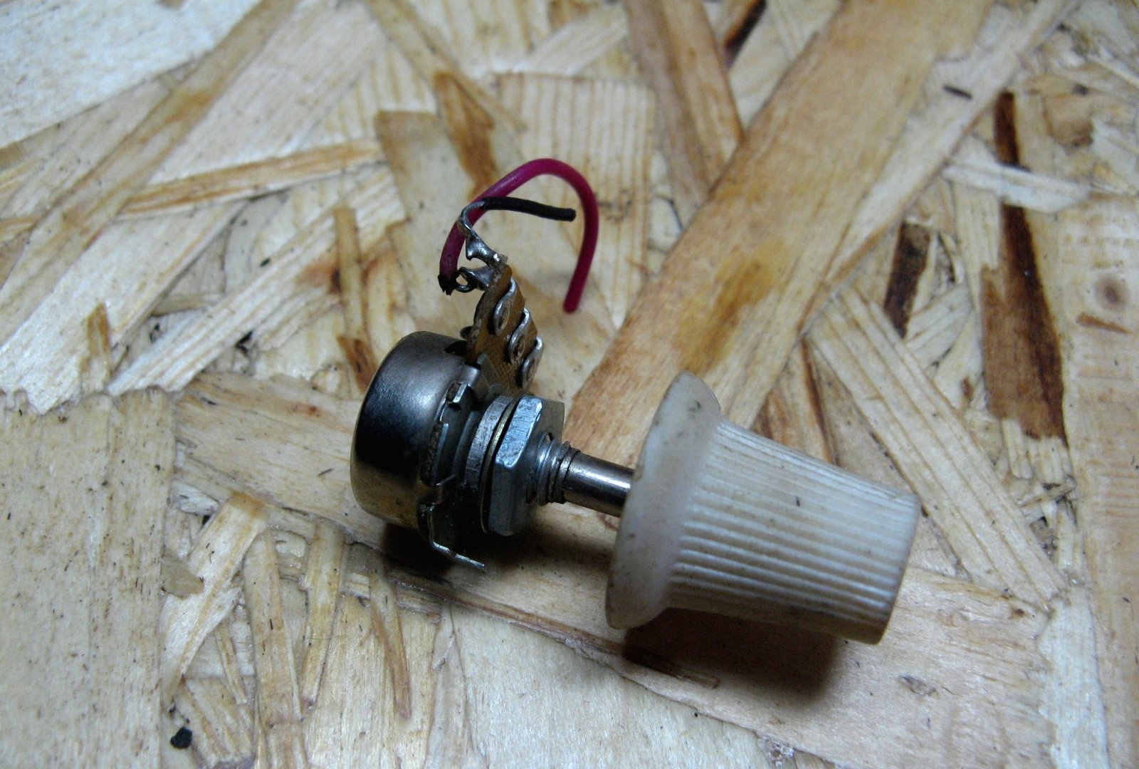
For comfortable adjustment of the output voltage, I will use a 4.7 kΩ adjustment resistor. 10 kOhm is installed on the board, but what I had, I’ll put one. The resistor is still the beginning of the 90s. With this rating, the adjustment is smooth. Just picked up a pen on him, also shaggy years.
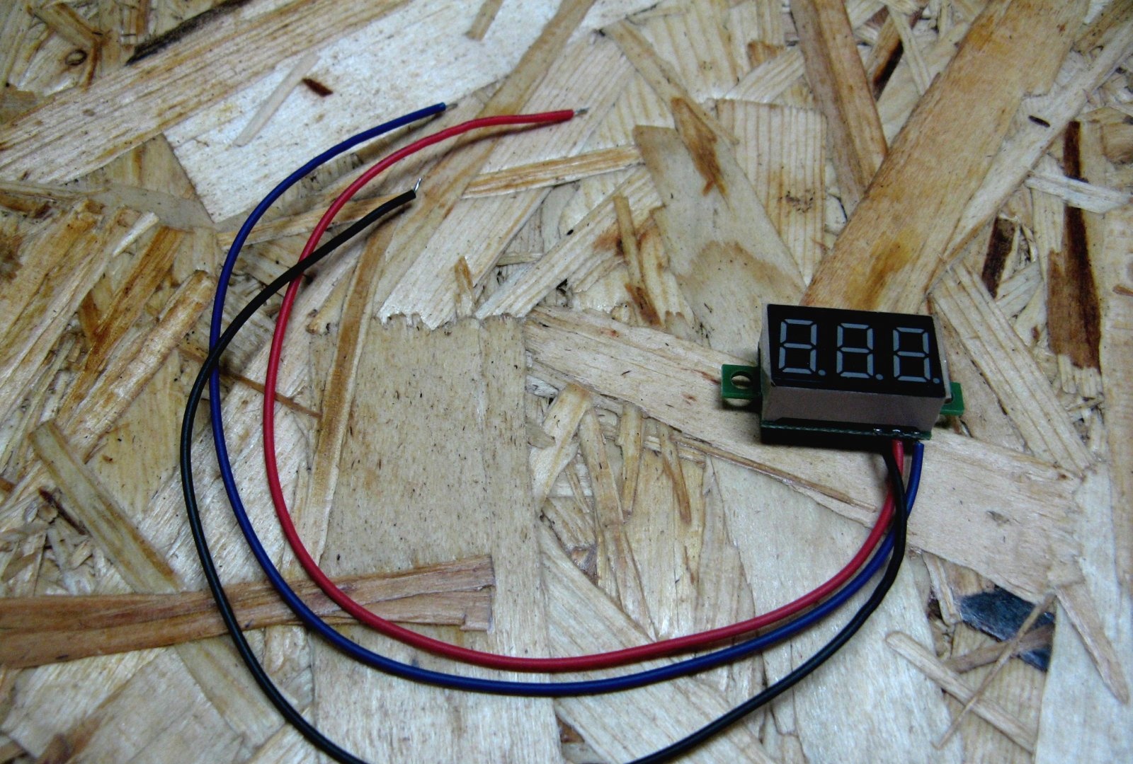
The output voltage indicator . He has three wires. Two wires power a voltmeter (red and black), and a third (blue) measuring one. You can connect red and blue together. Then the voltmeter will be powered by the output voltage of the unit, that is, the indication from 4 volts will light up. Agree, it’s not convenient, so I will feed it separately, more on that later.
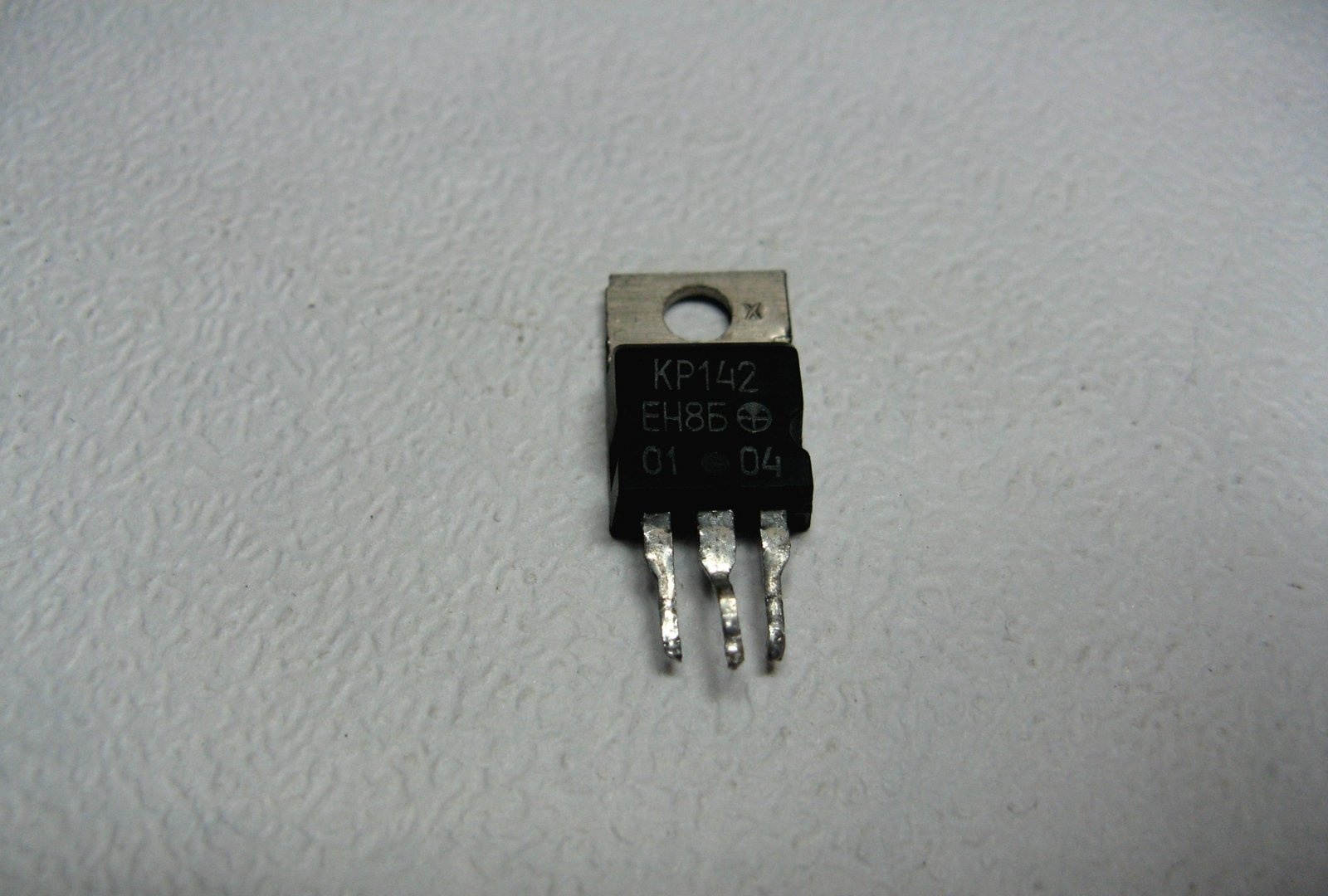
To power the voltmeter, I will use a domestic voltage regulator chip for 12 volts. This will ensure the operation of the indicator-voltmeter from a minimum. The voltmeter is fed through red plus and black minus. Measurement is carried out through black minus and blue plus block output.
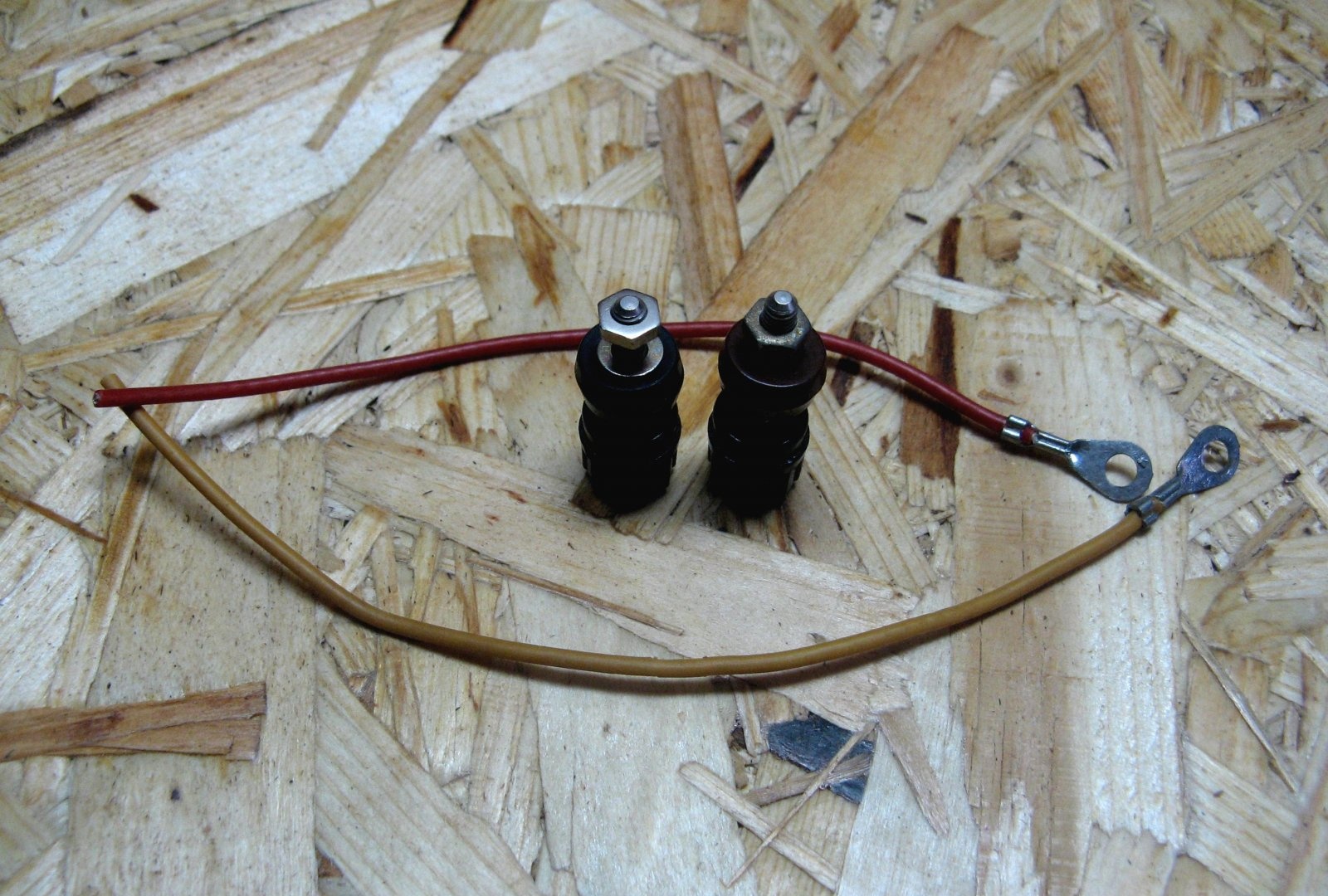
I have domestic terminals. They have holes for banana plugs and holes for clamping wires. Similar . Just picked up wires with ferrules.
Power supply assembly
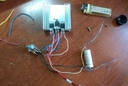
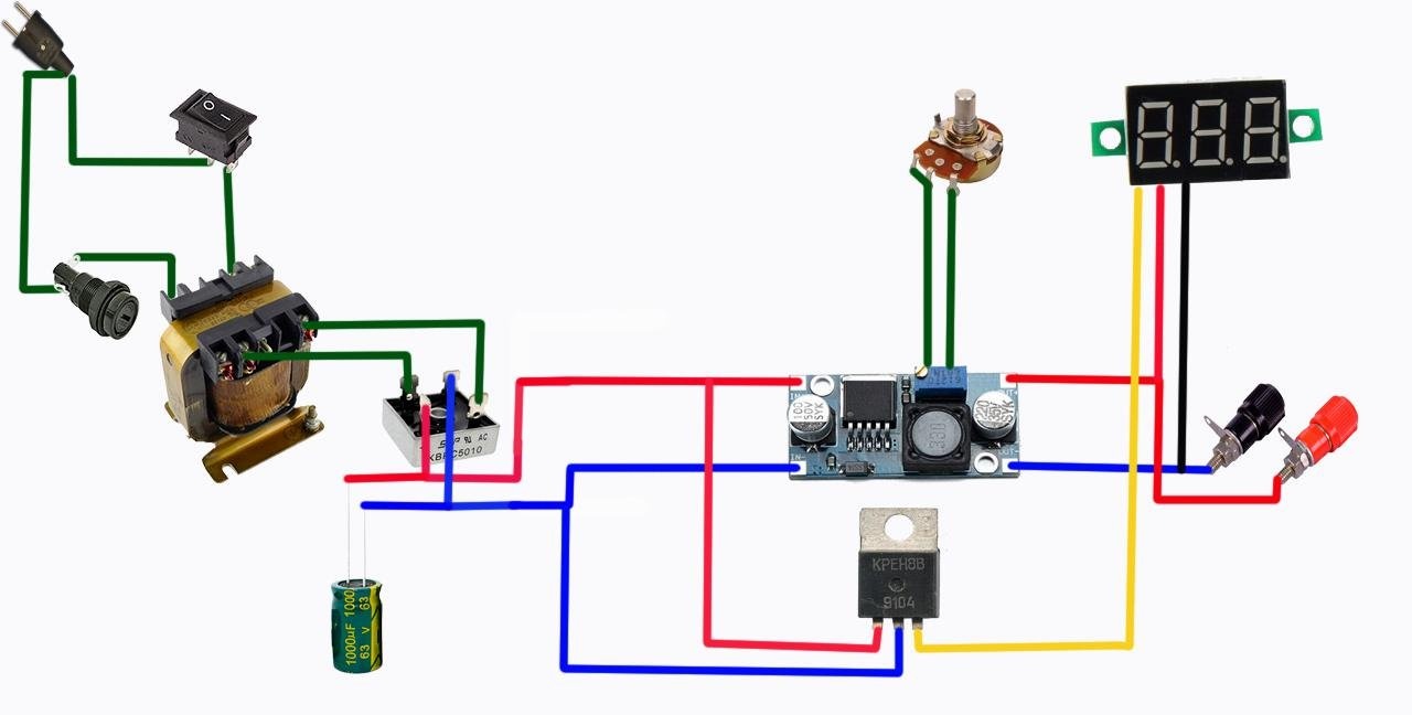
Everything is going according to a simple sketched scheme.
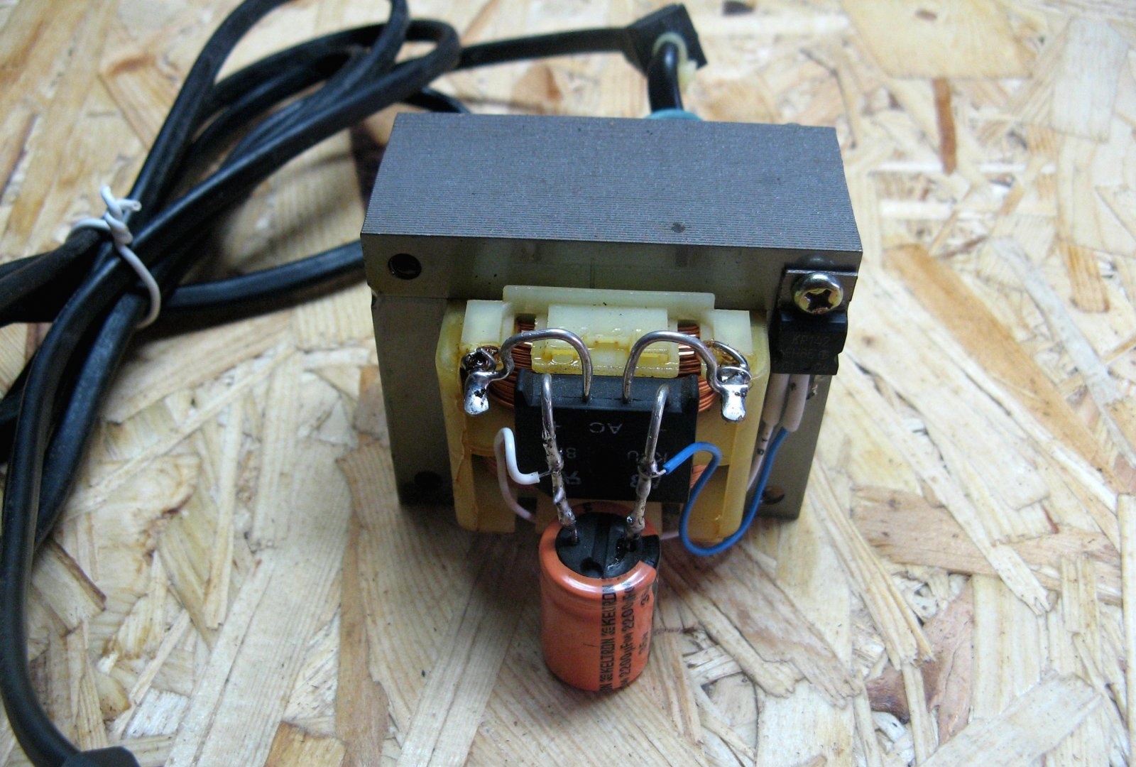
The diode bridge must be soldered to the transformer. I bent it for a comfortable installation. A capacitor was soldered to the output of the bridge. It turned out not to go beyond the dimensions in height.

I screwed the power supply of the voltmeter to the transformer. In principle, it does not heat up, and so it stands in its place and does not bother anyone.
On the regulator board, a resistor was soldered and two wires were wired under the external resistor. I also soldered the wires under the output terminals.
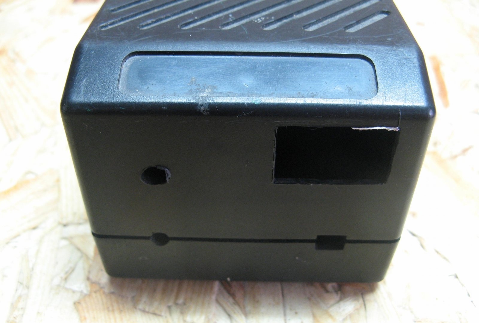
On the case, marking holes for everything that will be on the front panel. Cut holes for a voltmeter and one terminal. I install the resistor and the second terminal on the junction of the box. When assembling the box, everything is fixed by squeezing both halves.
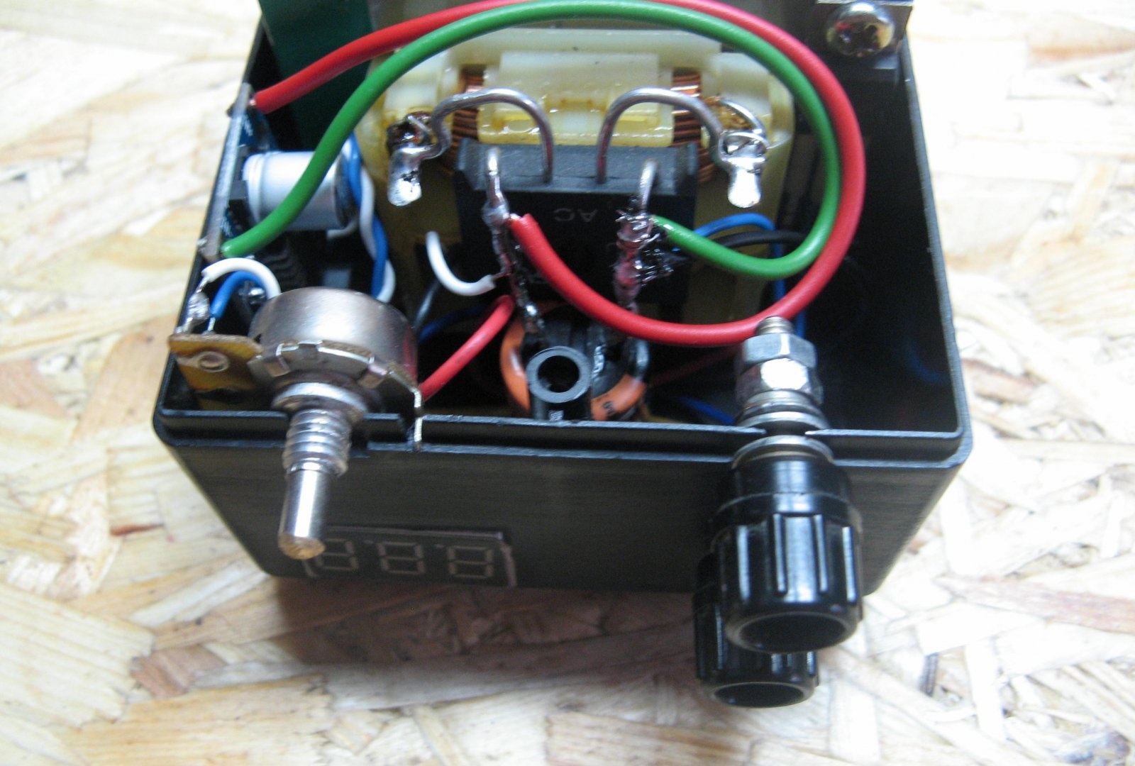
The terminal and voltmeter are installed.
It so happened to install a second terminal and an adjustment resistor. Turnkey made a cutout of the resistor.
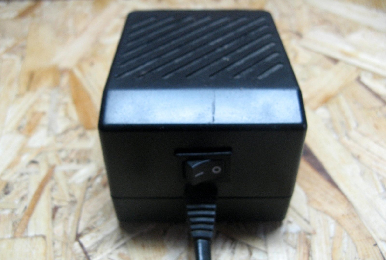
Cut a window under the switch. We assemble and close the case.It remains only to unsolder the switch and the adjustable power supply is ready for use.
Block test
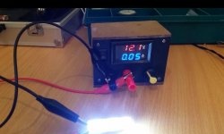
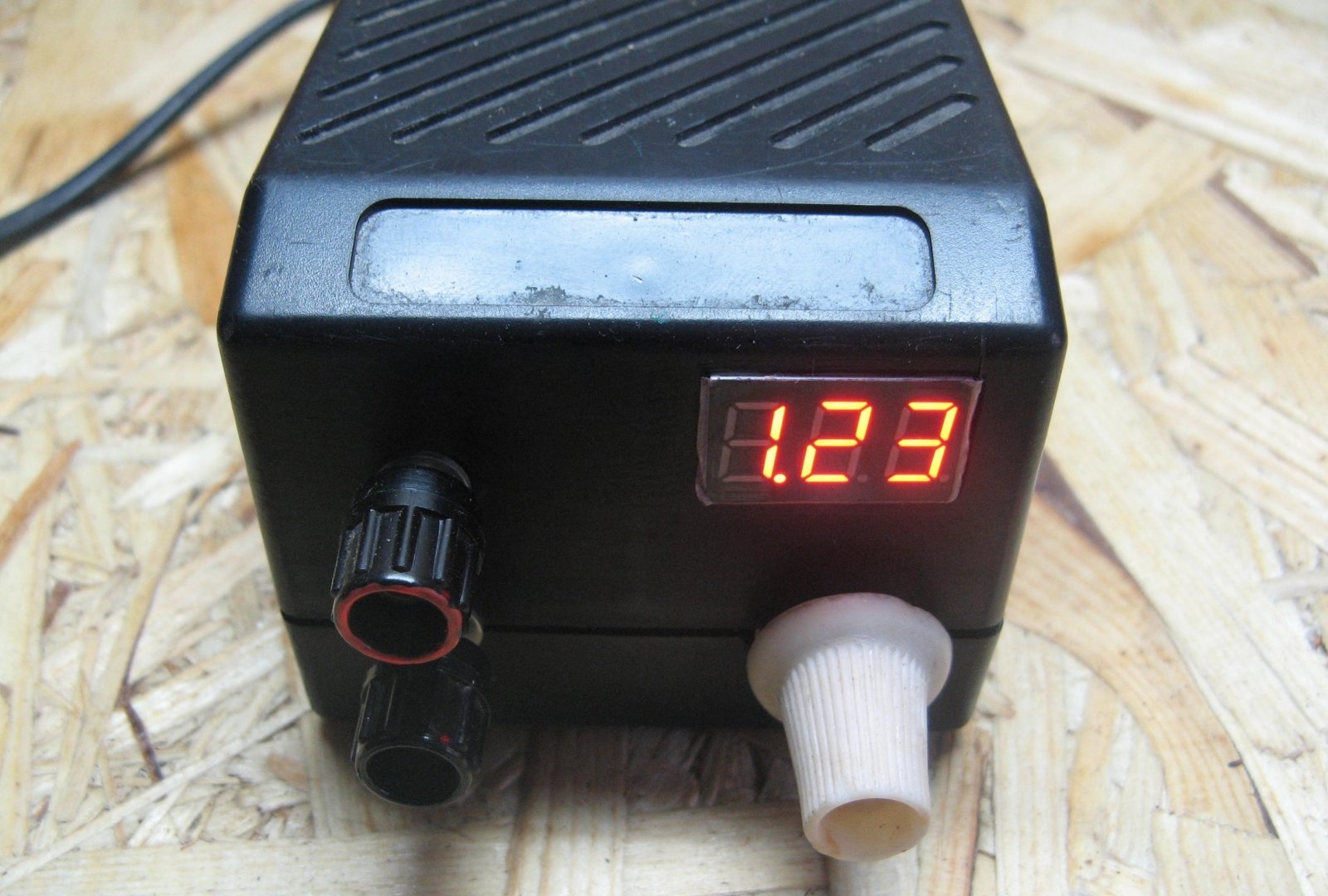
The power supply regulates the voltage from 1.23 Volts.
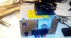
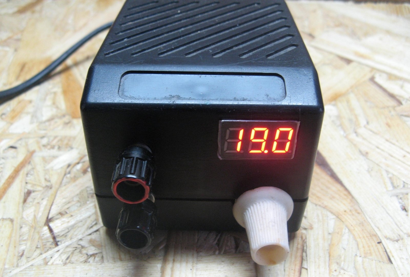
The maximum voltage is 19 volts.
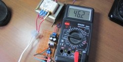
The voltmeter displays are pretty accurate. 20-30 millivolts do not consider such a strong deviation.
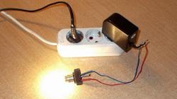
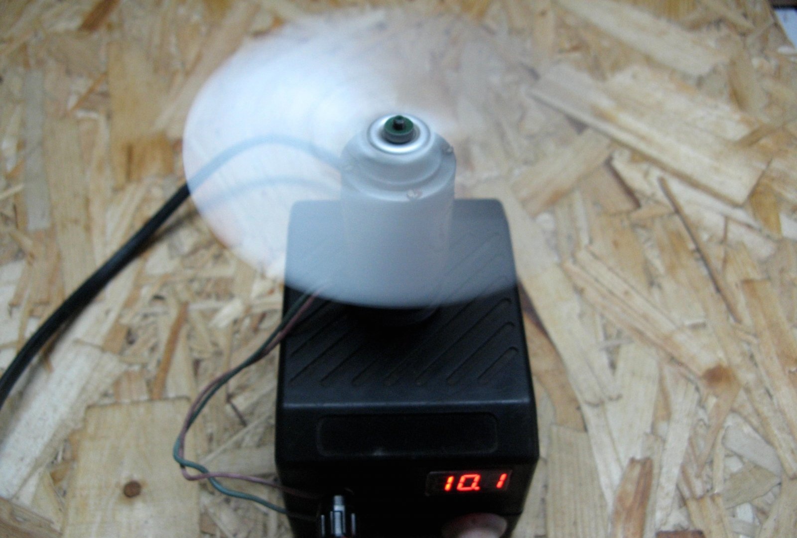
Connected a motor. The voltage does not sag.
This power supply is simple and does not display the load current. Maybe this is a minus, but this case would not accommodate an ammeter and current regulation is not provided. So I coped with the task.
Such an adjustable power supply turned out. This design is simple and easy to repeat for everyone. Details are not rare.
Good luck in manufacturing!