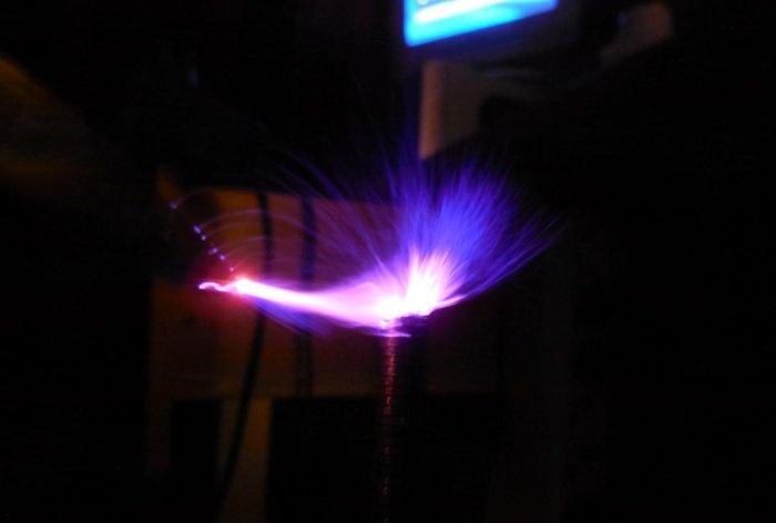
A very interesting device called the “Brovin Kacher” is very popular among radio amateurs. With its help you can observe spectacular corona discharges, lightning, and plasma arcs. Many people on the Internet call the kacher a Tesla coil, but these are two completely different devices with different operating principles. In this article we will talk specifically about the Brovin quality device, perhaps the simplest high-voltage device that you can think of.
Brovin's quality scheme
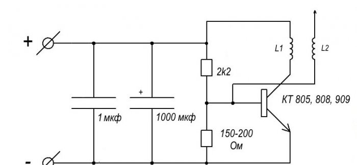
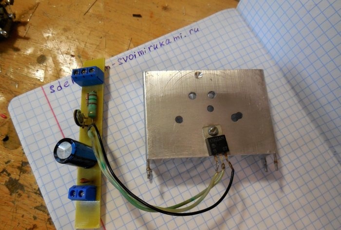
The circuit is extremely simple, containing only one transistor, a pair of resistors and a pair of capacitors. Capacitors serve to filter the supply voltage, one of them should be electrolytic with a large capacity (470-2200 µF), and the second ceramic or film with a low capacitance (0.1-1 µF), to smooth out high-frequency interference. Two resistors form a voltage divider, one of them should have a small resistance (150-200 Ohms), and the second should have about 10-20 times more resistance. In this case, a trimming resistor can be placed in series with the high-resistance resistor to adjust the quality to the maximum discharge length.There is a mounting location for it on the printed circuit board attached to the article. The transistor in the circuit can be used in almost any powerful n-p-n structure. Transistors KT805, KT808, KT809 have proven themselves well. You can also experiment with field ones and install, for example, IRF630, IRF740. The length of the discharges largely depends on the choice of transistor. The transistor must be installed on a radiator, because it generates a large amount of heat. L1 in the diagram is the primary coil, and L2 is the secondary coil, the high-voltage discharge is removed from it.
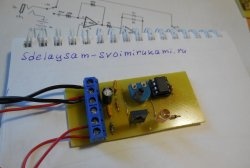
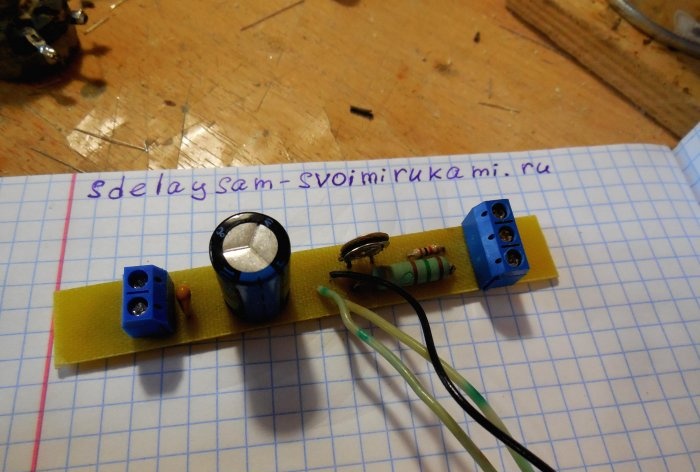
Device board
The payment is made using the LUT method, a printable file is attached. Terminal blocks are provided on the board to connect power wires and coil outputs.
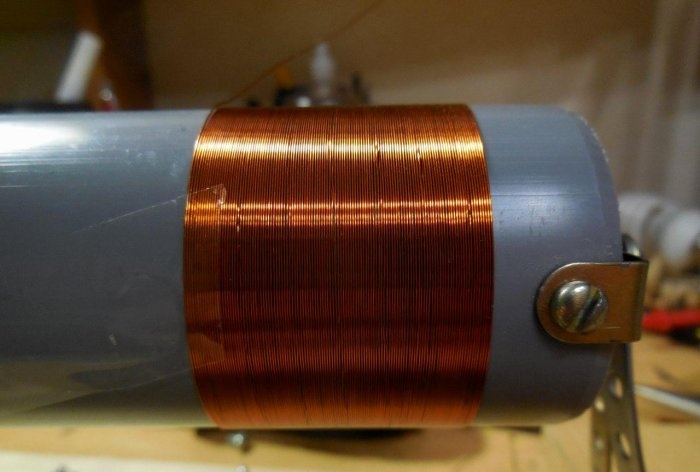
Manufacturing of a secondary (high voltage) coil
First of all, you need to make a secondary coil. With it, everything is simple and concrete - the more turns, the greater the voltage, and, accordingly, the longer the discharges. You can use enameled copper wire with a cross section of 0.1 - 0.3 mm. It is very convenient to use a sewer pipe as a frame for the secondary winding; the optimal diameter is 5-7 cm. You need to wind the wire turn to turn, as carefully as possible. It is advisable to use a single piece of wire so that there are no joints. But if the wire breaks during the process, it’s okay, you can solder the torn piece to it, carefully insulate it and continue winding the turns, it will work in any case.
To speed up the winding process, you can install the pipe on two supports on the left and right so that it rotates freely on them. This will make winding the wire much easier.If you need to leave during work, you can secure the tip of the wire with tape, then you can come back, peel off the tape and continue winding. Under no circumstances should you let go of the tip of the wire, otherwise the tension will disappear, the turns will separate and you will have to start all over again.
After the coil is wound, the turns of wire must be fixed to the pipe. It is best to use a transparent varnish, then the reel will look very beautiful. I coated the coils with regular wax, it did the job, now it will be much more difficult to accidentally damage the thin wire.
A regular wire should be soldered to the lower end of the wire and carefully fixed at the edge of the pipe.
At the upper edge of the pipe there is a so-called “terminal” - the place from which the corona discharge will “emanate”. It is advisable to make it sharp, then the discharge will be concentrated at the tip of the needle. I secured a bolt to the edge of the pipe, and screwed a dart tip onto the bolt, as can be seen in the photo. The secondary coil is ready.
Making the Primary Coil
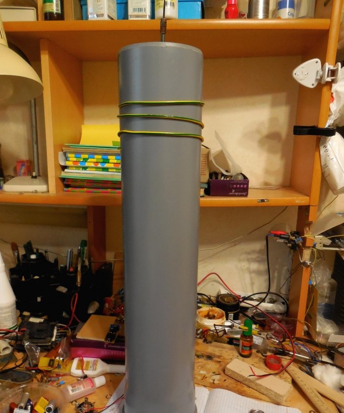
The primary coil contains 2-5 turns of thick copper wire, with a cross-section of 1.5 - 2.5 mm. It should be located around the secondary coil, its diameter should be 2-3 cm larger. For the frame of the primary coil, you can again use a sewer plastic pipe, you just need to take a piece of pipe with a diameter and length greater than for the secondary one. At a distance of 10 cm from the top of the pipe, two holes are drilled through which the copper wire is threaded. The length of the discharge strongly depends on the number of turns, so their number is selected experimentally.
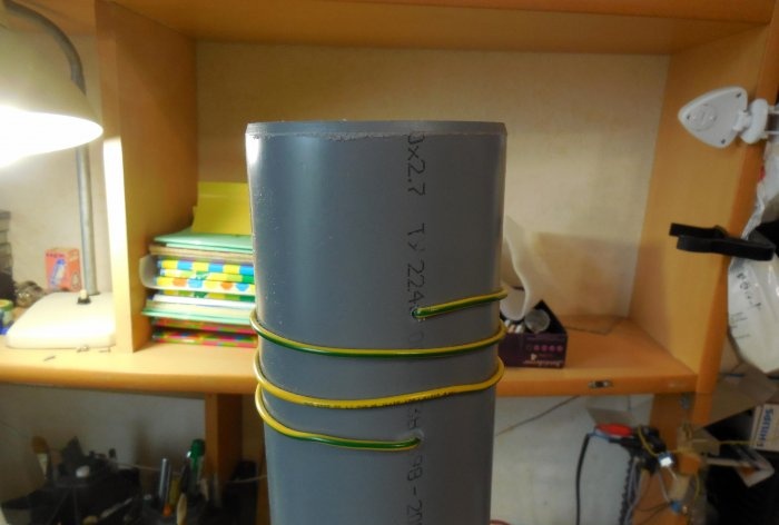
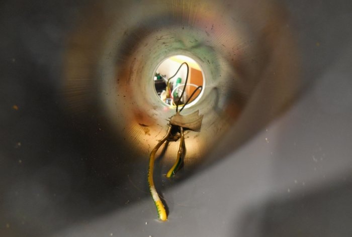
The wire from the turns themselves must be brought to the bottom of the coil, passing them inside the pipe. Be sure to fix it with glue.The primary coil is ready.
Assembling the Brovin quality
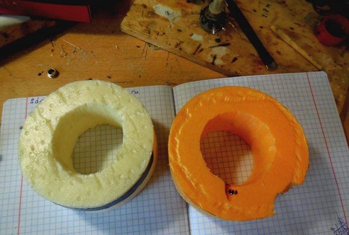
After the coils are wound, you can put everything together. Two round pieces with holes in the center are cut out of penoplex. The secondary coil should fit tightly into the central hole, and the outer diameter of the workpieces should match the diameter of the primary coil.
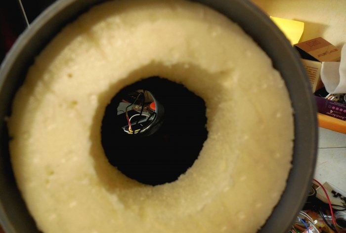
We place the round blanks inside the large pipe, and then insert the secondary coil into them. If necessary, you need to fix them with glue. The wire from the secondary coil must be routed to the bottom of the large pipe.
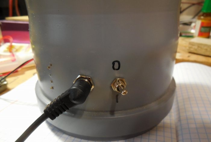
Two holes are drilled at the bottom of the large pipe, one for the power connector, the second for the toggle switch.
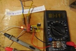
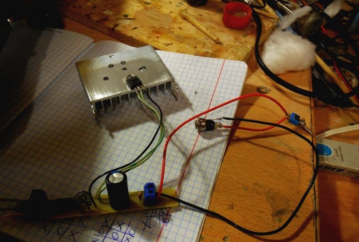
Now all that remains is to connect the board to the power supply, placing a toggle switch in the positive wire gap, and connect the coil leads.
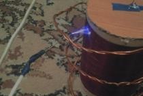
When all wires are connected, you can check the functionality of the device. Carefully apply voltage to the board. If a small light appears on the terminal, it means the camera is working. If the kacher refuses to work even when the supply voltage increases, the leads of the primary coil should be swapped. Now you can experiment with the number of turns in the primary coil, move the coils relative to each other, finding a position at which the discharge will be maximum. The power supply voltage range of the camera is very wide - a small discharge appears already at 12 volts. As the voltage increases, it increases, and along with it, the heat dissipation on the transistor increases. Therefore, it is imperative to monitor the temperature of the radiator, because an overheated transistor will not work for a long time.
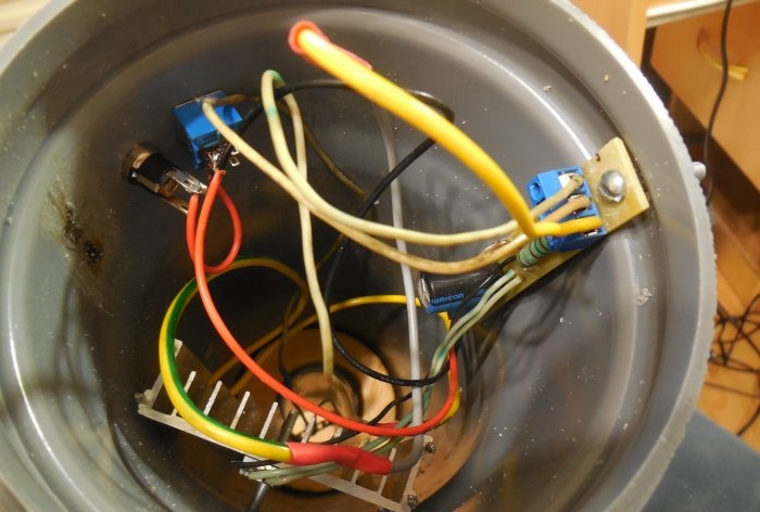
The last thing that remains is to install the board with the radiator inside the large pipe, in its lower part, and place the toggle switch with the connector in the already drilled holes.
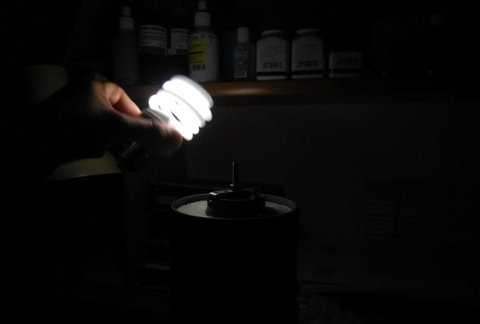
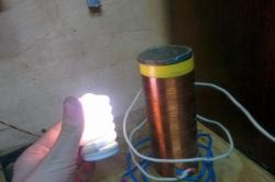
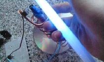
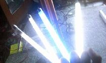
This camera looks very impressive even when turned off. You can touch the corona discharge with your finger, it is quite safe, because the current from such a discharge flows along the surface of the skin without penetrating inside. This effect is called the skin effect, it occurs due to the high frequency of the camera. During long-term operation, a large amount of ozone is released, so you should turn on the power generator only in ventilated areas. Also, do not forget about the strong electromagnetic radiation that is created around the device. It can damage other electronic devices, so you should not leave phones, cameras, or tablets nearby. The electromagnetic field created is so strong that gas-discharge (or, more simply put, energy-saving) light bulbs light up on their own near the coil.