As you know, laziness is the engine of progress. It’s impossible to count how many different electronic devices people have developed in order to automate their lives. Automation has penetrated into all spheres of human life and now sometimes we are even too lazy to get up and turn on the light with a regular switch. It doesn’t matter - an acoustic switch was invented just for this case: you just have to clap your hands and the light will come on, or the music will start playing, or some other electrical device will turn on. Any person with basic skills in working with a soldering iron can make such an acoustic switch.
Device diagram
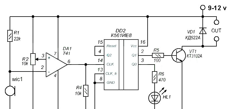
An electronic microphone, designated “mic1” in the diagram, converts mechanical air vibrations into electrical ones, which trigger the circuit. Here you can use any electronic microphone of sufficient sensitivity; you can get them, for example, from ordinary cheap computer microphones or headsets.The trimming resistor R2 in the diagram sets the response sensitivity; it must be selected experimentally, based on the sensitivity of the selected microphone and the noise level of the room. The DA1 chip is a regular operational amplifier that works as a comparator. You can use any pinout that is suitable, for example, TL071, TL081, UA741. Resistor R4 pulls the op-amp output to negative, thereby preventing false positives. The DD2 chip works as a trigger, providing a stable either on or off state at the output of the circuit. You can use the domestic K561IE8 or its imported analog CD4017. Light-emitting diode indicates the load status – if Light-emitting diode lights up, it means the log is being held at the output. 1 (on state) if Light-emitting diode is extinguished, which means the output is log. 0 (off state). The transistor in the circuit switches the load; here you can use any low-power NPN transistors, for example, BC547, KT3102, KT315. A relay can be connected to the OUT output, which, in turn, can control a powerful load - lighting lamps or electrical appliances. If the load is something low-power, powered by direct current, for example, separate LEDs or LED strip, it can be connected directly to the circuit at the OUT output, observing the polarity. In this case, it is worth installing a more powerful transistor, for example, KT817.
Details
To create an acoustic switch you do not need any expensive or scarce things; everything can be bought at a radio parts store. Resistor values are not so critical; they can be changed within 30%. It is advisable to purchase sockets for microcircuits so that they can be used in the future in other circuits.
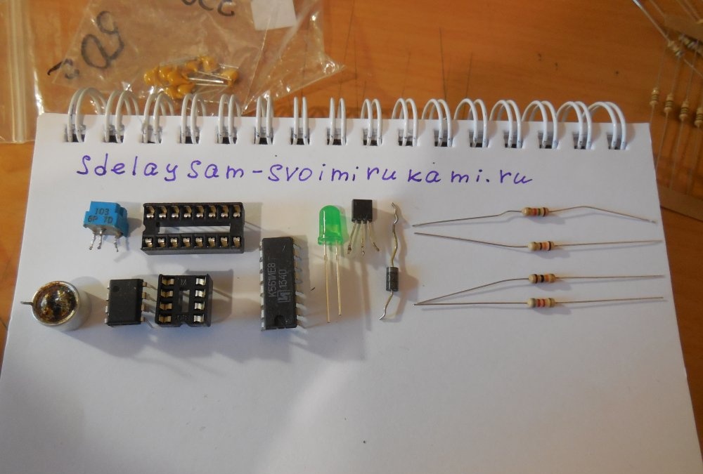
Parts List:
- Resistors: 22 kOhm, 10 kOhm, 470 Ohm, 100 Ohm.
- Microcircuits UA741, K561IE8.
- Light-emitting diode at 3 volts.
- Diode KD521.
- Transistor BC547.
- Electret microphone.
Assembling an acoustic switch - switch
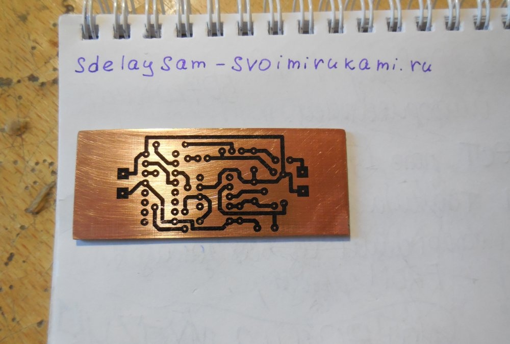
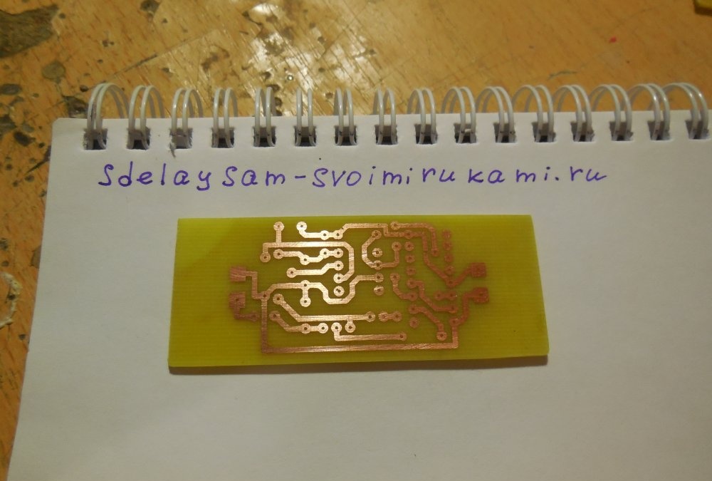
First of all, you need to make a printed circuit board. It is made using laser-iron technology, which is known to many radio amateurs. The PCB file for the Sprint-Layout program is included; there is no need to mirror it before printing.
Download the board:
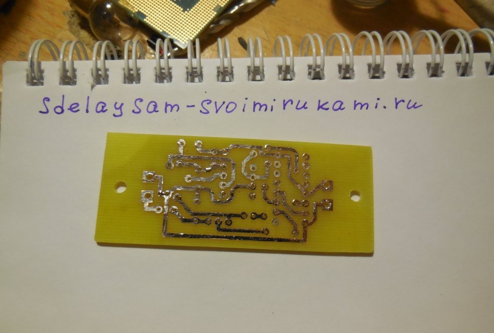
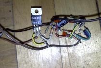
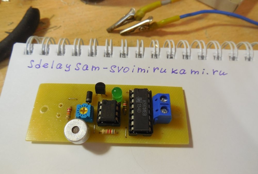
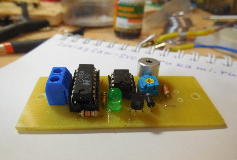
Once the PCB is drilled and tinned, you can begin soldering parts into it. The first step is to install resistors, a diode, and then everything else. The microphone can be soldered directly into the board, or it can be wired out, but you should not move the microphone away from the board itself at a great distance, otherwise the influence of external noise will affect and the circuit will not work properly. After soldering all components, be sure to check the correct installation and test adjacent tracks for short circuits, if necessary. It is imperative to wash off the flux from the board, because it can also interfere with the correct operation of the circuit.
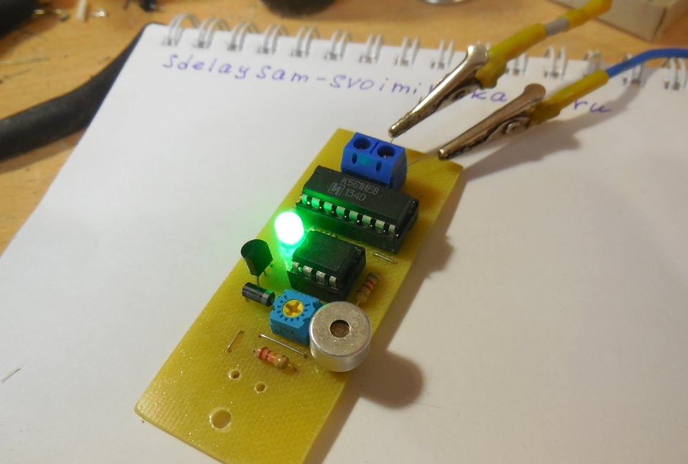
Circuit Breaker Tests
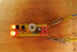
After a thorough check of the board, you can supply power to it - a constant voltage of 9-12 volts. If nothing smokes and the LED lights up, then everything is assembled correctly. Now all that remains is to twist the trimming resistor, setting the desired response sensitivity. Do not make the switch too sensitive, otherwise it will be triggered by any extraneous noise.The ideal option, in my opinion, is if it is triggered by a light clap near the microphone, then it will not react to extraneous noise.
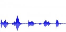
Watch the video of work
The operation of the switch is clearly shown in the video: