In everyday life, we most often encounter power supplies that lower the high voltage in the network to several volts, which are necessary to connect various devices. However, you can do the inverse transformation. Moreover, the scheme is completely uncomplicated.
It can come in handy in two cases:
- In order to connect equipment and devices that are powered from only 220 volts in the field.
- In case of power outages.
Well, do not forget that experimenting is always entertaining. For example, I assembled this design simply out of interest, without an aim for practical application.
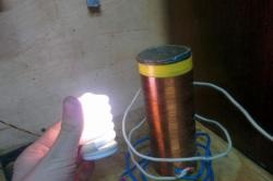
True, it should be noted that the presented converter is of low power and will not withstand a large load, such as a TV. However, as will be seen in the example, an energy-saving light bulb works from it.
Transducer Fabrication
We need only a few details:
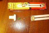
- Transformer from an old phone charger.
- Transistor 882P or its domestic analogues KT815, KT817.
- Diode IN5398, an analogue of KD226 or any other one designed for reverse current up to 10 volts of medium or high power.
- Resistor (resistance) at 1 kOhm.
- Small breadboard.
Naturally, you will need a soldering iron with solder and flux, wire cutters, wires and a multimeter (tester). You can, of course, make a printed circuit board, but for a circuit of several details, you should not waste time developing track layouts for their drawing and etching of foil textolite or getinaks. We check the transformer. The board of the old charger.
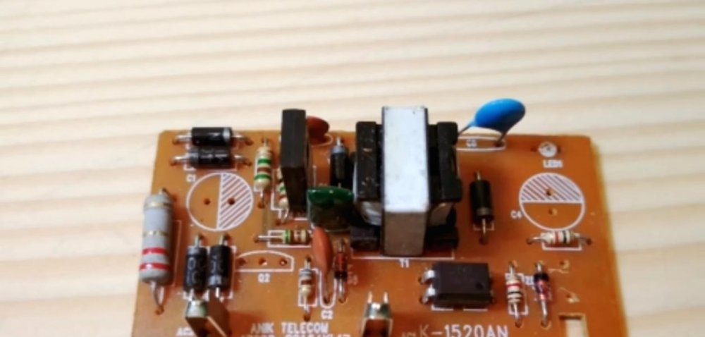
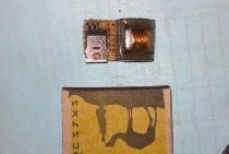
The soldered transformer.
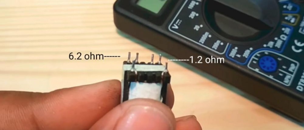
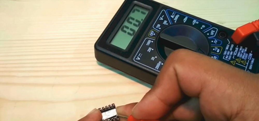
Next, we need to check the transformer and find the conclusions of its windings. We take a multimeter, switch it to ohmmeter mode. In turn, we check all the conclusions, we find those that are a couple of "call" and record their resistance.
1. The first 0.7 Ohm.
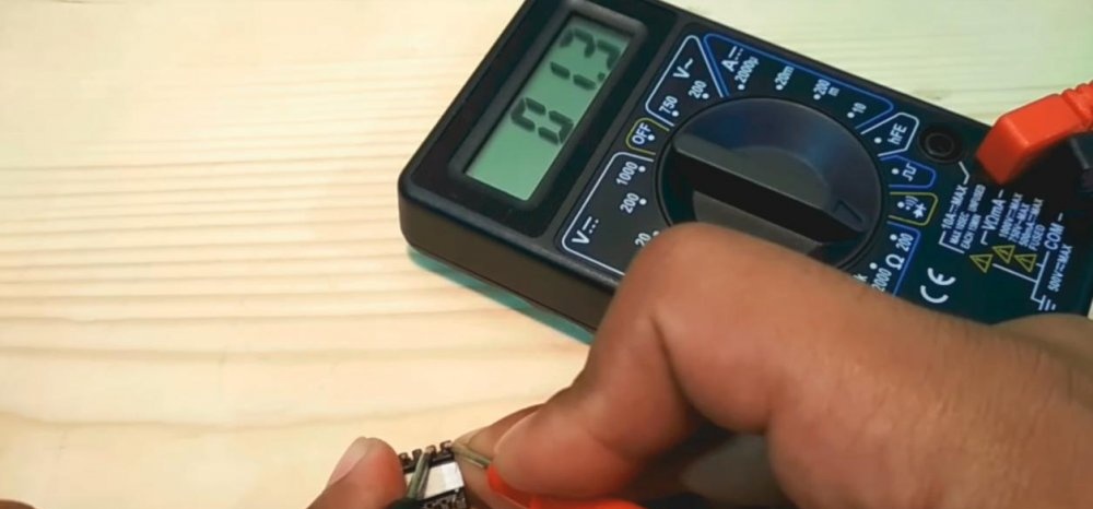
2. The second is 1.3 ohms.
3. The third is 6.2 ohms.
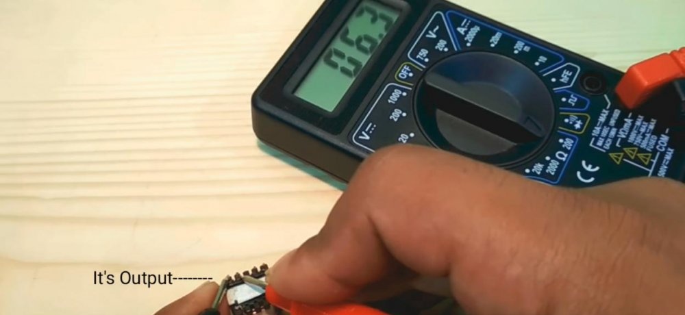
That winding, in which the greatest resistance was primary, 220 V was supplied to it. In our device it will be secondary, that is, an output. The rest was relieved undervoltage. With us, they will serve as the primary (the one with a resistance of 0.7 ohms) and part of the generator (with a resistance of 1.3). The measurement results for different transformers may vary, you need to focus on their relationship between each other.
Device diagram
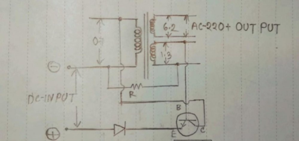
As you can see, it is the simplest. For convenience, we marked the resistance of the windings. The transformer cannot convert direct current. Therefore, a generator is assembled on the transistor and one of its windings. It supplies a pulsating voltage from the input (battery) to the primary winding, a voltage of about 220 volts is removed from the secondary.
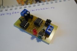
We assemble the converter
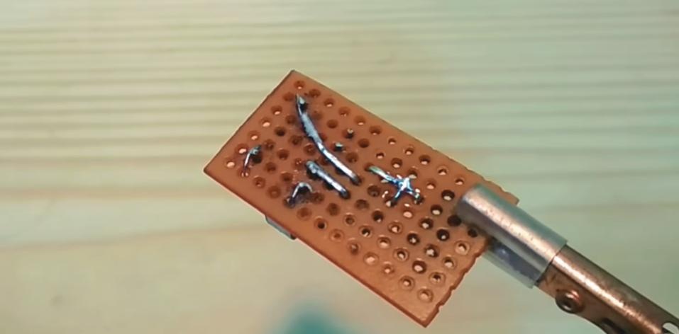
We take a breadboard.

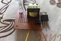
We install a transformer on it. Choose a resistor of 1 kilo-ohm. We insert it into the holes of the board, next to the transformer. We bend the terminals of the resistor so as to connect them with the corresponding contacts of the transformer. Solder it. At the same time, it is convenient to fix the board in any clamp, as in the photo, so that the problem of the missing "third hand" does not arise. Soldered resistor.We bite the extra length of the output. A board with bitten resistor leads. Next we take the transistor. We install it on the board on the other side of the transformer, as in the screenshot (I selected the locations of the parts so that it is more convenient to connect them according to the circuit diagram). We bend the transistor leads. Solder them. Installed transistor. Take a diode. We install it on the board parallel to the transistor. We solder. Our scheme is ready.
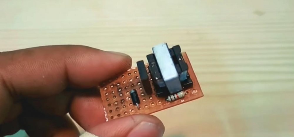
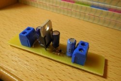
Solder the wires to connect a constant voltage (DC input). And wires for pulsating high voltage (AC output).

For convenience, we take 220 volt wires with crocodiles.

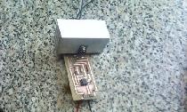
Our device is ready.
Testing the converter
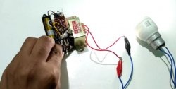
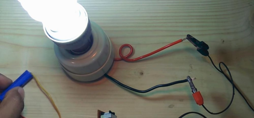
In order to apply voltage, we select a 3-4 volt battery. Although you can use any other power source.
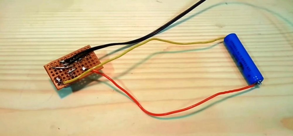
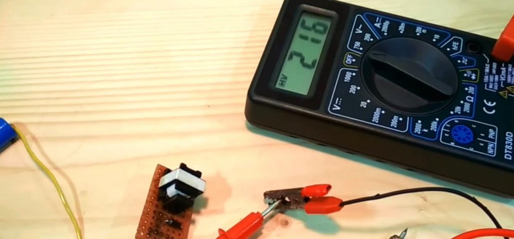
Solder the low voltage input wires to it, observing the polarity. We measure the voltage at the output of our device. It turns out 215 volts.
Attention. It is not advisable to touch the parts when the power is connected. This is not so dangerous if you have no health problems, especially with your heart (although two hundred volts, but the current is weak), but it can be unpleasant to “pinch”.
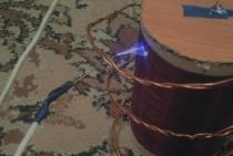
We complete the test by connecting a 220 volt fluorescent energy-saving lamp. Thanks to the "crocodiles" this is easy to do without a soldering iron. As you can see, the lamp is on.
Our device is ready.
Tip. You can increase the power of the converter by installing a transistor on the radiator.
True battery capacity is not enough for long. If you are going to constantly use the converter, then select a more capacious battery and make a case for it.