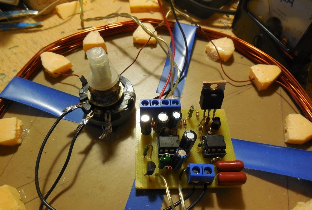
This article will focus on the creation of the most popular, sought after, time-tested, reliable pulse metal detector called "Pirate". It allows you to find coins in the ground at a depth of 15-20 cm and large objects at a distance of up to 1.5 m. The scheme of the metal detector is presented below.
Scheme metal detector "Pirate"
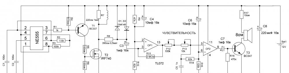
The entire circuit can be conditionally divided into two parts - a transmitter and a receiver. The NE555 microcircuit generates rectangular pulses, which are fed to the coil through a powerful field-effect transistor. When the coil interacts with the metal near it, complex physical phenomena occur, due to which the receiving part has the ability to "see" if there is metal in the coil area or not. The receiver circuit in the original Pirate circuit is the Soviet K157UD2, which is now becoming quite difficult to get. However, instead of it, you can use the modern TL072, while the parameters of the metal detector will remain exactly the same. The circuit board proposed in this article is designed specifically for installing the TL072 chip (they have different pinouts).
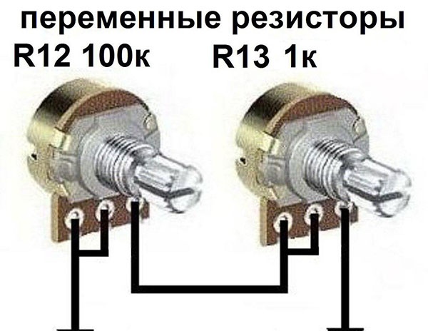
Capacitors C1 and C2 are responsible for the formation of the frequency of rectangular pulses, their capacitance must be stable, so it is advisable to apply film. Resistors R2 and R3 are responsible for the duration and frequency of the rectangular pulses that the chip forms. From its output, they arrive at the transistor T1, are inverted and fed to the gate of the field-effect transistor. Any sufficiently powerful field effect transistor with a drain-source voltage of at least 200 volts can be used here. For example, IRF630, IRF740. Diodes D1 and D2 are any low-power, for example, KD521 or 1N4148. Between 1 and 6 of the output of the microcircuit, a variable resistor of 100 kOhm is turned on, with which the sensitivity is set. It is most convenient to use two potentiometers, 100 kOhm for coarse tuning and 1-10 kOhm for fine tuning. You can connect them as follows:
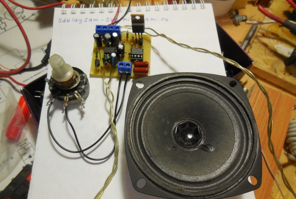
The speaker in the circuit is connected in series with a 10-47 ohm resistor. The lower its resistance, the louder the sound and the greater the consumption of the metal detector. Transistor T3 can be replaced with any other low-power NPN transistor, for example, domestic KT3102. The speaker can be used any, the first one. So, let's move on from words to deeds.
Metal detector assembly
Parts List
Chips:
- NE555 - 1 pc.
- TL072 - 1 pc.
Transistors:
- BC547 - 1 pc.
- BC557 - 1 pc.
Capacitors:
- 100 nF - 2 pcs.
- 1 nF - 1 pc.
- 10 microfarads - 2 pcs.
- 1 microfarad - 2 pcs.
- 220 uF - 1 pc.
Resistors:
- 100 kOhm - 1 pc.
- 1.6 kOhm - 1 pc.
- 1 kOhm - 1 pc.
- 10 Ohm - 2 pcs.
- 150 Ohm - 1 pc.
- 220 Ohm - 1 pc.
- 390 Ohm - 1 pc.
- 47 kOhm - 2 pcs.
- 62 kOhm - 1 pc.
- 2 megohms - 1 pc.
- 120 kOhm - 1 pc.
- 470 kOhm - 1 pc.
Rest:
- Speaker 1 - pcs.
- Diodes 1N4148 - 2 pcs.
- DIP8 Sockets - 2 pcs.
- 100 kOhm potentiometer - 1 pc.
- Potentiometer 10 kOhm - 1 pc.
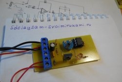
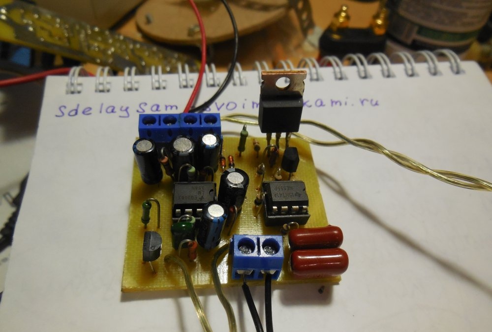
Printed circuit board
The printed circuit board is performed by the LUT method, it is not necessary to mirror it before printing.
[11.66 Kb] (downloads: 1613)
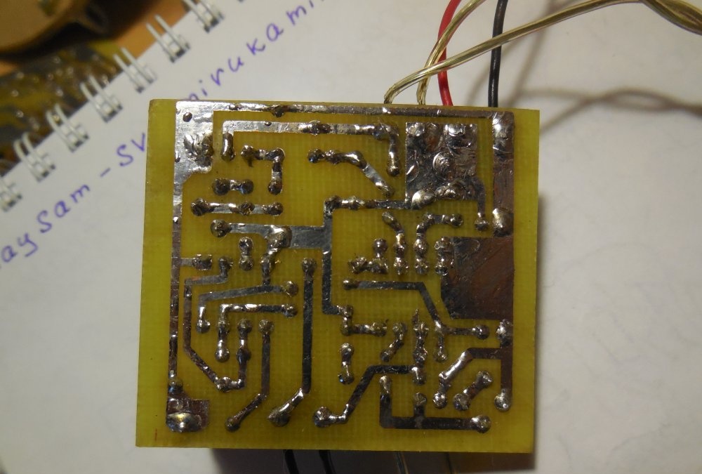
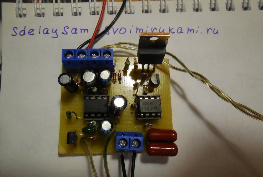
On the board, first of all, you need to solder the resistors, diodes, then everything else. It is desirable to install microcircuits in the sockets. The wires for connecting the coil, speaker, potentiometer and coil can be soldered directly to the board, but it is more convenient to use screw terminal blocks, then it will be possible to connect and disconnect the wires without using a soldering iron.

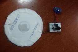
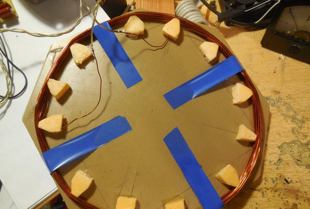
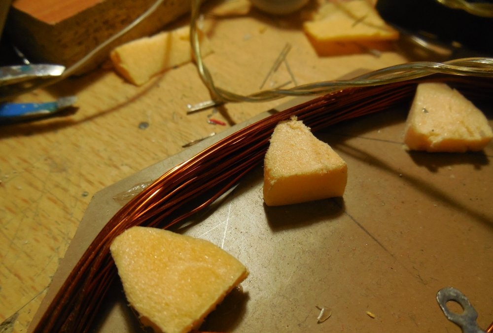
Coil manufacturing
A few words about the search coil. The most optimal option is to wind 20-25 turns of copper wire with a cross section of 0.5 mm2 on a round frame with a diameter of about 20 cm. Sensitivity depends to a large extent on the number of turns, so you should first wind more turns, about 30 pieces, and then gradually reduce the number of turns , choose a number at which the sensitivity will be maximum. The wires from the board from the coil should not be long, preferably copper and with a cross section no smaller than the cross section of the coil wire.
Metal detector setup
After assembling the board, winding the coil, the device can be turned on. In the first 5-10 seconds after turning on, various noises and cods will be heard from the speaker, this is normal. Then, when the operational amplifier enters its operating mode, you need to find a mode with the potentiometer when individual clicks will come from the speaker. When you bring a metal object to the coil, the click frequency will increase significantly, and if you add metal to the very center of the coil, the trust will turn into a continuous hum. If the sensitivity is not enough, and changing the number of turns of the coil does not help, it is worth trying to pick up the values of the resistors R7, R11, changing them up or down. The board must be washed away from the flux, often it becomes the cause of the improper operation of the metal detector. Successful assembly!