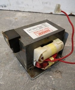
When creating various electronic devices, sooner or later the question arises of what to use as a power source for homemade electronics. Let's say you've assembled some kind of LED flasher, now you need to carefully power it from something. Very often, for these purposes, various phone chargers, computer power supplies, and all kinds of network adapters are used, which do not in any way limit the current supplied to the load.
What if, say, on the board of this same LED flasher, two closed tracks accidentally went unnoticed? By connecting it to a powerful computer power supply, the assembled device can easily burn out if there is any installation error on the board. It is precisely to prevent such unpleasant situations from happening that there are laboratory power supplies with current protection. Knowing in advance approximately how much current the connected device will consume, we can prevent short circuits and, as a result, burnout of transistors and delicate microcircuits.
In this article we will look at the process of creating just such a power supply to which you can connect a load without fear that something will burn out.
Power supply diagram
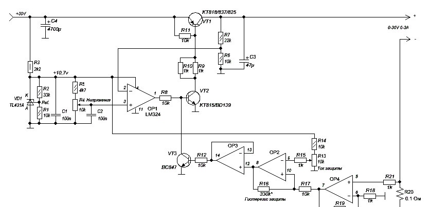
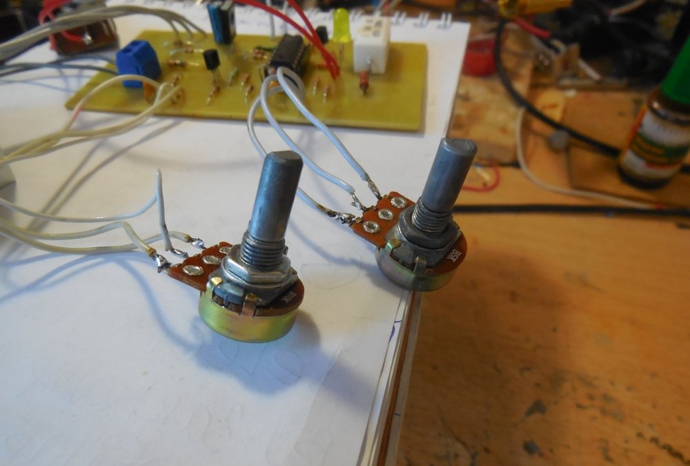
The circuit contains an LM324 chip, which combines 4 operational amplifiers; a TL074 can be installed instead. Operational amplifier OP1 is responsible for regulating the output voltage, and OP2-OP4 monitor the current consumed by the load. The TL431 microcircuit generates a reference voltage approximately equal to 10.7 volts; it does not depend on the value of the supply voltage. Variable resistor R4 sets the output voltage; resistor R5 can be used to adjust the voltage change frame to suit your needs. Current protection works as follows: the load consumes current, which flows through a low-resistance resistor R20, which is called a shunt, the magnitude of the voltage drop across it depends on the current consumed. Operational amplifier OP4 is used as an amplifier, increasing the low voltage drop across the shunt to a level of 5-6 volts, the voltage at the output of OP4 varies from zero to 5-6 volts depending on the load current. The OP3 cascade works as a comparator, comparing the voltage at its inputs. The voltage at one input is set by variable resistor R13, which sets the protection threshold, and the voltage at the second input depends on the load current. Thus, as soon as the current exceeds a certain level, a voltage will appear at the output of OP3, opening transistor VT3, which, in turn, pulls the base of transistor VT2 to ground, closing it. The closed transistor VT2 closes the power VT1, opening the load power circuit. All these processes take place in a matter of seconds.
Resistor R20 should be taken with a power of 5 watts to prevent its possible heating during long-term operation. Trimmer resistor R19 sets current sensitivity; the higher its value, the greater sensitivity can be achieved. Resistor R16 adjusts the protection hysteresis; I recommend not to get carried away with increasing its value. A resistance of 5-10 kOhm will ensure a clear latching of the circuit when the protection is triggered; a higher resistance will give a current limiting effect when the voltage at the output does not completely disappear.
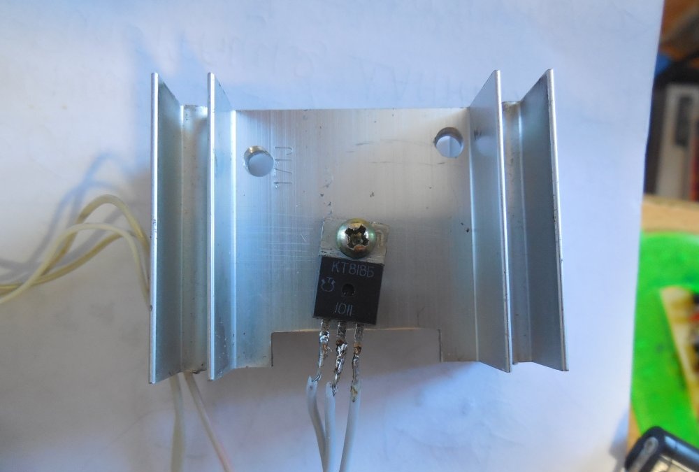
As a power transistor, you can use domestic KT818, KT837, KT825 or imported TIP42. Particular attention should be paid to its cooling, because the entire difference between the input and output voltage will be dissipated in the form of heat on this transistor. That is why you should not use a power supply with a low output voltage and high current, as the heating of the transistor will be maximum. So, let's move from words to action.
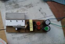
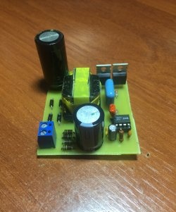
PCB fabrication and assembly
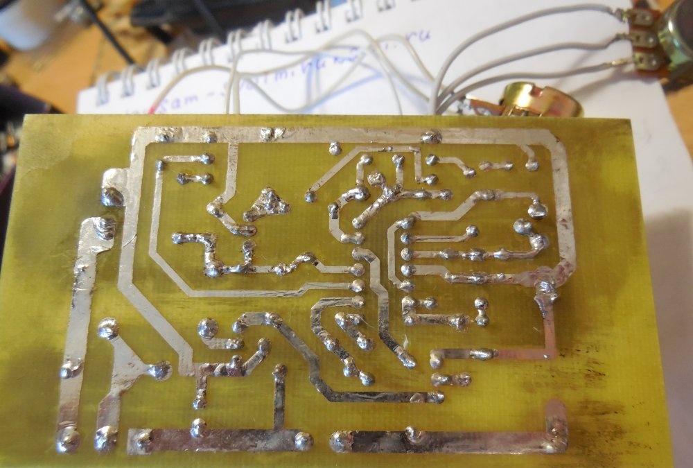
The printed circuit board is made using the LUT method, which has been described many times on the Internet.
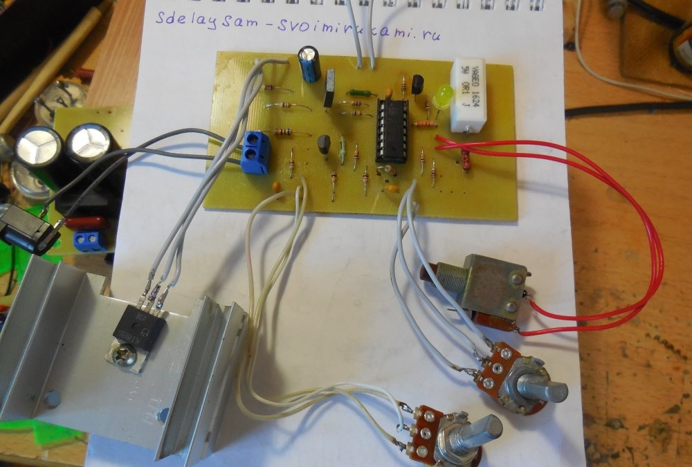
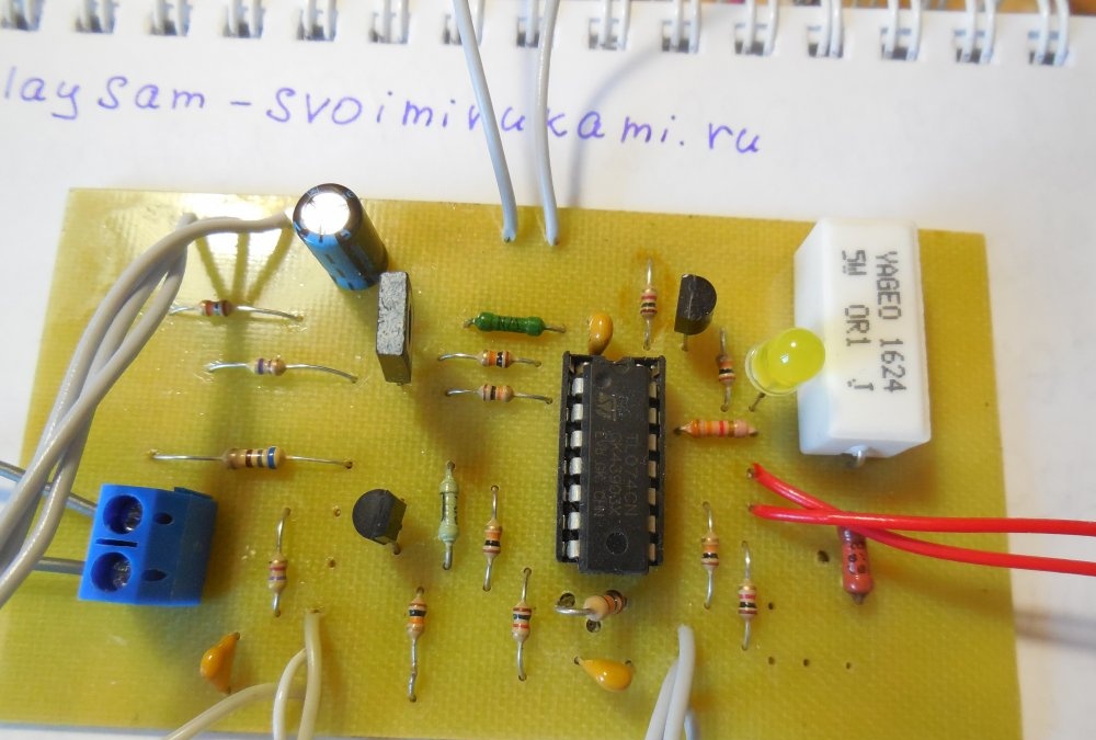
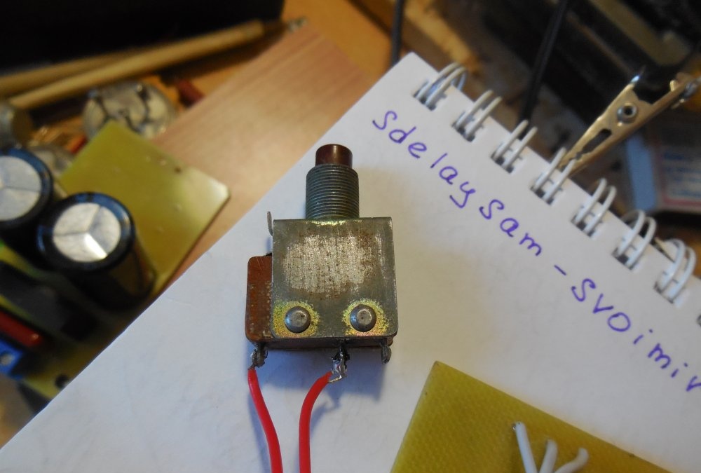
Added on PCB Light-emitting diode with a resistor that is not indicated in the diagram. Resistor for LED A value of 1-2 kOhm is suitable. This Light-emitting diode turns on when the protection is triggered. Two contacts have also been added, marked with the word “Jamper”; when they are closed, the power supply comes out of the protection and “snaps off”. In addition, a 100 pF capacitor has been added between pins 1 and 2 of the microcircuit; it serves to protect against interference and ensures stable operation of the circuit.
Setting up the power supply
So, after assembling the circuit, you can begin to configure it.First of all, we supply power of 15-30 volts and measure the voltage at the cathode of the TL431 chip, it should be approximately equal to 10.7 volts. If the voltage supplied to the input of the power supply is small (15-20 volts), then resistor R3 should be reduced to 1 kOhm. If the reference voltage is OK, we check the operation of the voltage regulator; when rotating the variable resistor R4, it should change from zero to maximum. Next, we rotate the resistor R13 in its most extreme position; the protection may be triggered when this resistor pulls the OP2 input to ground. You can install a 50-100 Ohm resistor between ground and the outermost pin of R13, which is connected to ground. We connect any load to the power supply, set R13 to its extreme position. We increase the output voltage, the current will increase and at some point the protection will work. We achieve the required sensitivity with trimming resistor R19, then you can solder a constant one instead. This completes the process of assembling the laboratory power supply; you can install it in the case and use it.
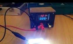
Indication

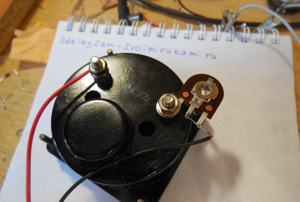
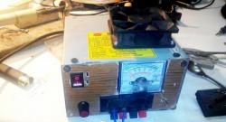
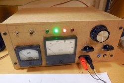
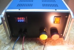
It is very convenient to use a pointer head to indicate the output voltage. Digital voltmeters, although they can show voltage up to hundredths of a volt, constantly running numbers are poorly perceived by the human eye. That is why it is more rational to use pointer heads. It is very simple to make a voltmeter from such a head - just place a trimming resistor in series with it with a nominal value of 0.5 - 1 MOhm. Now you need to apply a voltage, the value of which is known in advance, and use a trimming resistor to adjust the position of the arrow corresponding to the applied voltage. Happy build!