Circuits using microcontrollers are gaining quite a lot of popularity on the Internet. A microcontroller is a special chip that, in essence, is a small computer with its own input/output ports and memory. Thanks to a microcontroller, you can create very functional circuits with a minimum of passive components, for example, electronic clocks, players, various LED effects, and automation devices.
In order for the microcircuit to begin performing any functions, it needs to be flashed, i.e. load the firmware code into its memory. This can be done using a special device called a programmer. The programmer connects the computer on which the firmware file is located with the microcontroller being flashed. It is worth mentioning that there are microcontrollers of the AVR family, for example, Atmega8, Attiny13, and pic series, for example PIC12F675, PIC16F676. The Pic series belongs to Microchip, and the AVR series belongs to Atmel, so the firmware methods for PIC and AVR are different.In this article we will look at the process of creating an Extra-pic programmer, with which you can flash a pic series microcontroller.
The advantages of this particular programmer include the simplicity of its circuitry, reliability of operation, and versatility, because it supports all common microcontrollers. The computer is also supported by the most common firmware programs, such as Ic-prog, WinPic800, PonyProg, PICPgm.
Programmer circuit
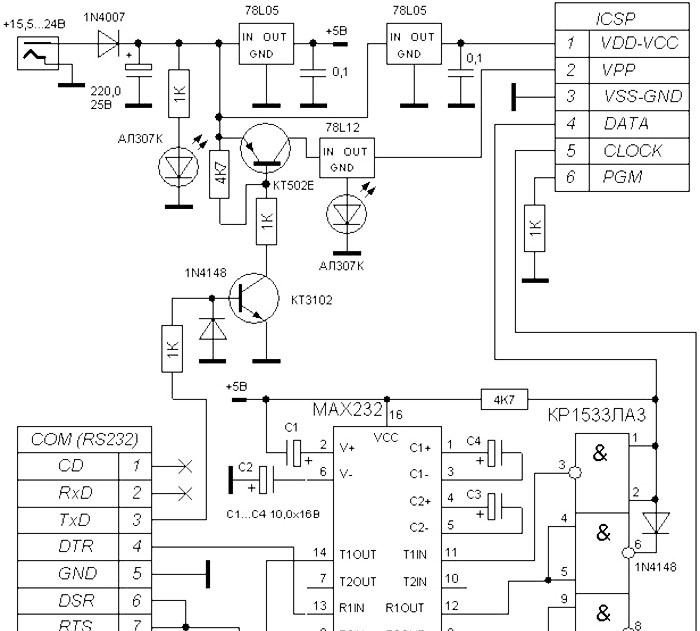
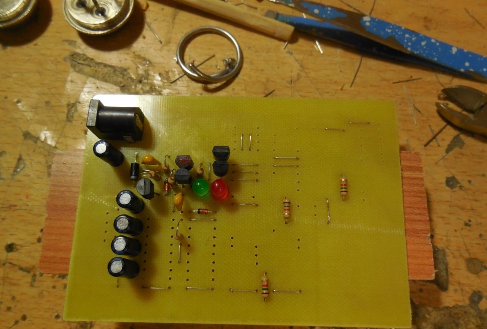
It contains two microcircuits, the imported MAX232 and the domestic KR1533LA3, which can be replaced with the KR155LA3. Two transistors, KT502, which can be replaced with KT345, KT3107 or any other low-power PNP transistor. KT3102 can also be changed, for example, to BC457, KT315. Green Light-emitting diode serves as an indicator of power availability, red lights up during the microcontroller firmware process. The 1N4007 diode is used to protect the circuit from the supply of voltage of incorrect polarity.
Materials
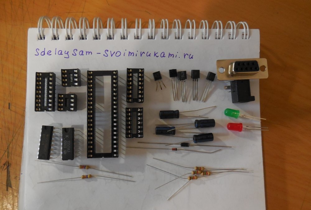
List of parts required to assemble the programmer:
- Stabilizer 78L05 – 2 pcs.
- Stabilizer 78L12 – 1 pc.
- Light-emitting diode at 3 in. green – 1 pc.
- Light-emitting diode at 3 in. red – 1 pc.
- Diode 1N4007 – 1 pc.
- Diode 1N4148 – 2 pcs.
- Resistor 0.125 W 4.7 kOhm – 2 pcs.
- Resistor 0.125 W 1 kOhm – 6 pcs.
- Capacitor 10 uF 16V – 4 pcs.
- Capacitor 220 uF 25V – 1 pc.
- Capacitor 100 nF – 3 pcs.
- Transistor KT3102 – 1 pc.
- Transistor KT502 – 1 pc.
- Chip MAX232 – 1 pc.
- Chip KR1533LA3 – 1 pc.
- Power connector – 1 pc.
- Female COM port connector - 1 pc.
- DIP40 socket – 1 pc.
- DIP8 socket – 2 pcs.
- DIP14 socket – 1 pc.
- DIP16 socket – 1 pc.
- DIP18 socket – 1 pc.
- DIP28 socket – 1 pc.
In addition, you need a soldering iron and the ability to use it.
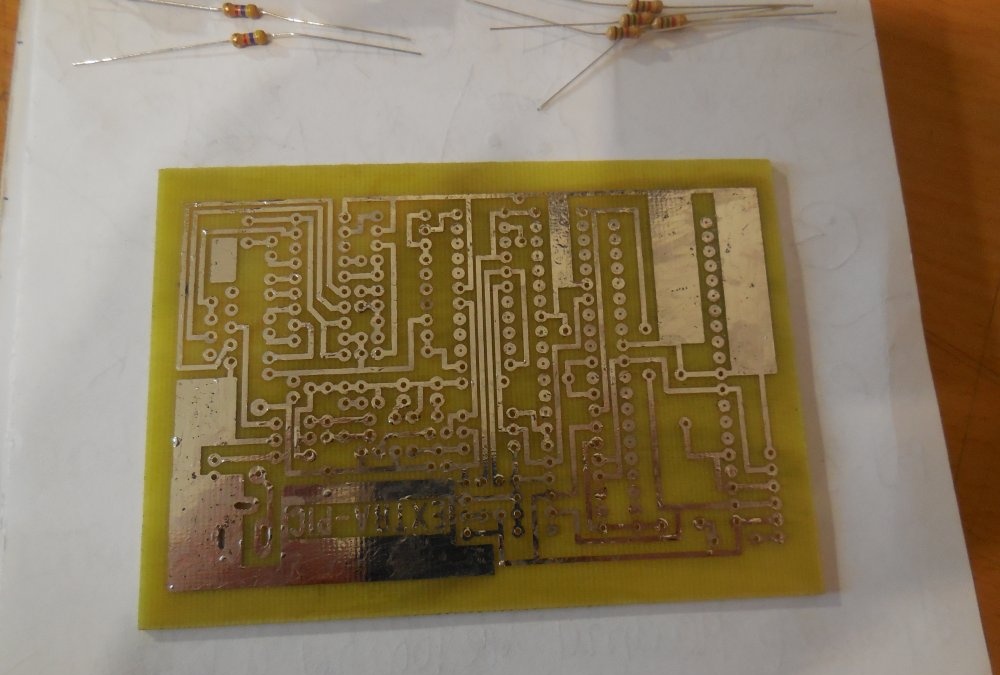
PCB manufacturing
The programmer is assembled on a printed circuit board measuring 100x70 mm. The printed circuit board is made using the LUT method, the file is attached to the article. There is no need to mirror the image before printing.
Download the board:
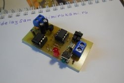
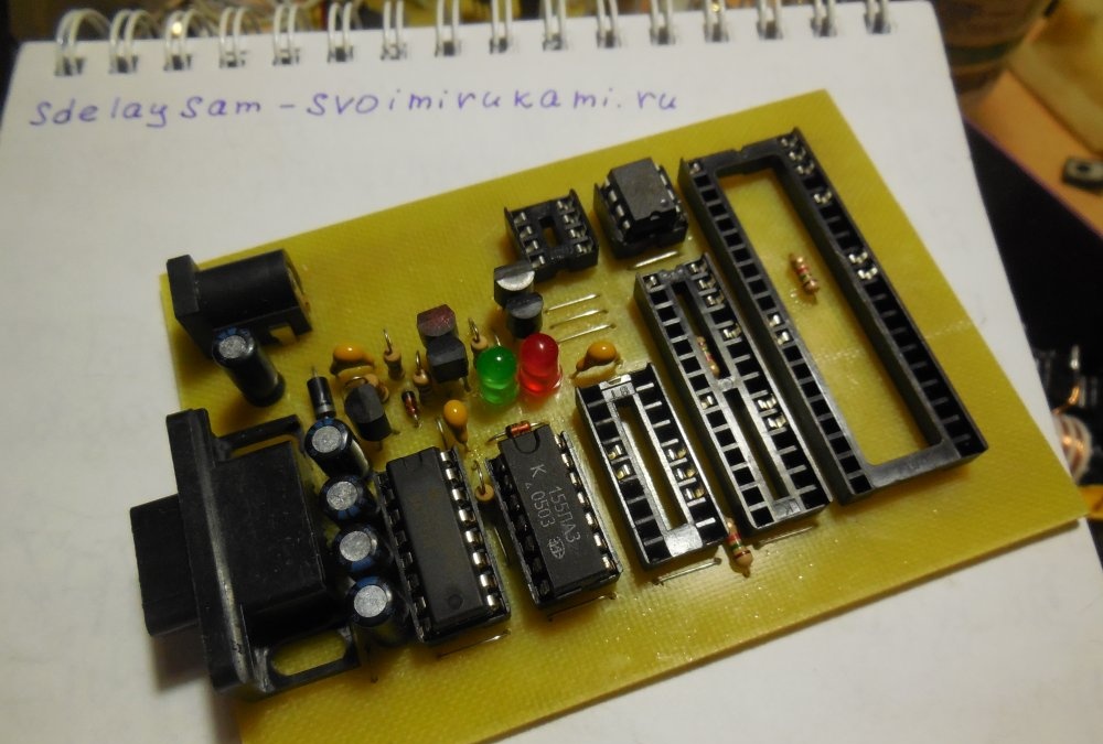
Programmer assembly
First of all, jumpers are soldered onto the printed circuit board, then resistors, diodes. Lastly, you need to solder the sockets and power connectors and COM port.
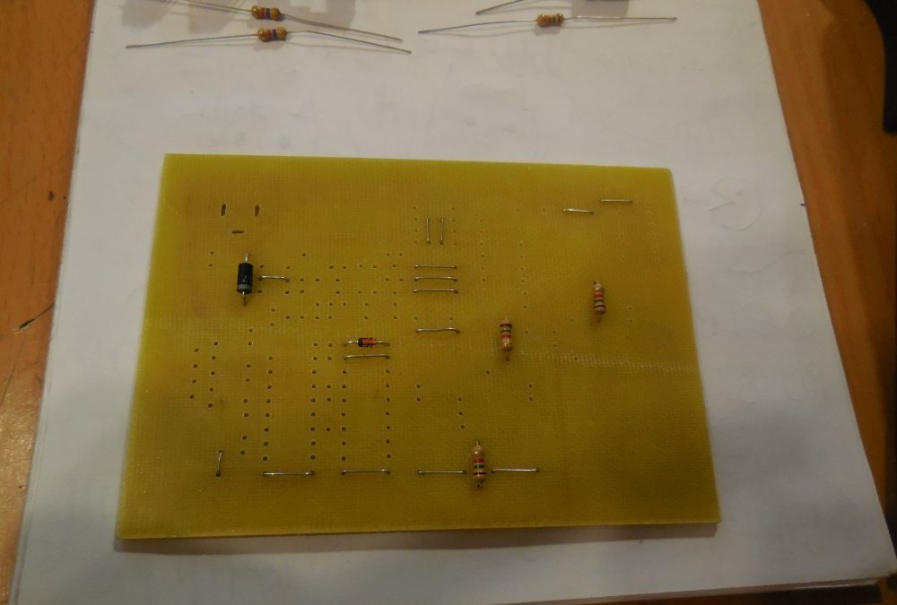
Because There are a lot of sockets on the printed circuit board for flashed microcontrollers, but not all of their pins are used; you can use this trick and remove unused contacts from the sockets. At the same time, less time will be spent on soldering and inserting a microcircuit into such a socket will be much easier.
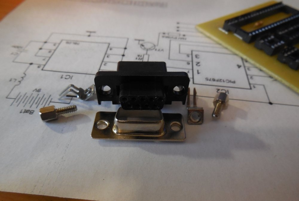
The COM port connector (called DB-9) has two pins that must be “stuck” into the board. In order not to drill extra holes on the board for them, you can unscrew the two screws under the sides of the connector, and the pins will fall off, as will the metal edging of the connector.
After soldering all the parts, the board must be washed from flux, and the adjacent contacts must be ringed to see if there are any short circuits. Make sure that there are no microcircuits in the sockets (you need to remove both MAX232 and KR1533LA3), connect the power. Check if there is a voltage of 5 volts at the outputs of the stabilizers. If everything is fine, you can install the MAX232 and KR1533LA3 microcircuits, the programmer is ready for use. The supply voltage of the circuit is 15-24 volts.
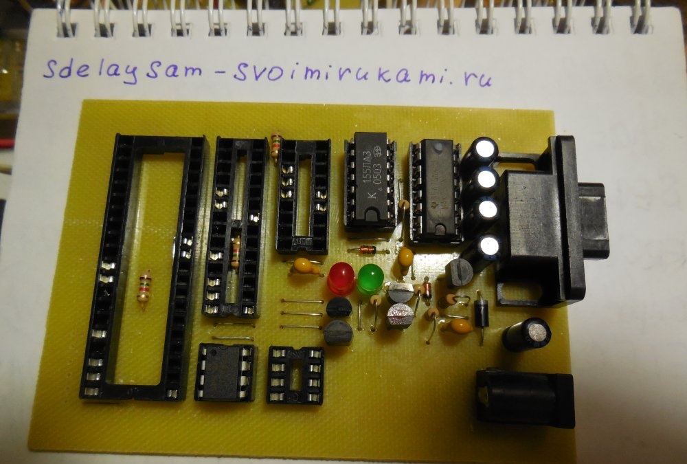
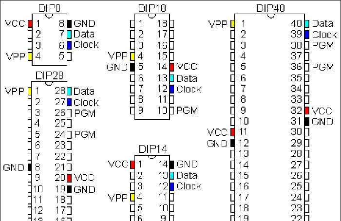
The programmer board contains 4 sockets for microcontrollers and one for flashing memory chips. Before installing the microcontroller to be flashed on the board, you need to check whether its pinout matches the pinout on the programmer board. The programmer can be connected to the computer's COM port directly or via an extension cable.Happy build!