Amplifier circuit
In this article, we will consider the assembly process of a very unusual amplifier operating in class “A” and containing only 4 transistors. This scheme was developed back in 1969 by the English engineer John Linsley Hood, despite its old age, to this day it remains relevant.
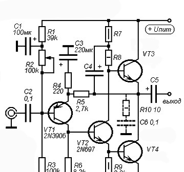
Unlike amplifiers on microcircuits, transistor amplifiers require careful tuning and selection of transistors. This scheme is no exception, although it looks extremely simple. Transistor VT1 - input, PNP structure. You can experiment with various low-power PNP transistors, including germanium, for example, MP42. Such transistors as 2N3906, BC212, BC546, KT361 have proven themselves well in this circuit as VT1. Transistor VT2 - NPN structures, medium or low power, KT801, KT630, KT602, 2N697, BD139, 2SC5707, 2SD2165 are suitable here. Particular attention should be paid to the output transistors VT3 and VT4, or rather, their gain. KT805, 2SC5200, 2N3055, 2SC5198 are well suited here. It is necessary to select two identical transistors with the closest possible gain, while it should be more than 120. If the gain of the output transistors is less than 120, then a transistor with high gain (300 or more) must be placed in the driver stage (VT2).
Amplifier ratings
Some values on the circuit are selected based on the supply voltage of the circuit and load resistance, some possible options are shown in the table:
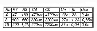
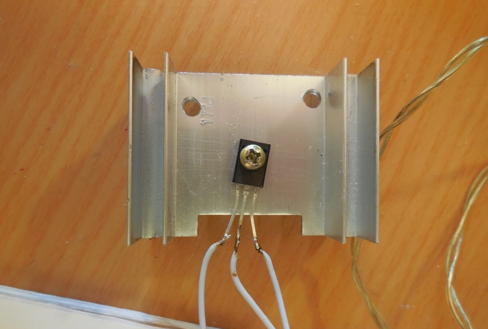
It is not recommended to raise the supply voltage of more than 40 volts, output transistors may fail. A feature of class A amplifiers is a large idle current, and, consequently, a strong heating of transistors. With a supply voltage, for example, 20 volts and a quiescent current of 1.5 amperes, the amplifier consumes 30 watts, regardless of whether a signal is supplied to its input or not. In this case, 15 watts of heat will be dissipated on each of the output transistors, and this is the power of a small soldering iron! Therefore, transistors VT3 and VT4 must be installed on a large radiator using thermal grease.
This amplifier is prone to the appearance of self-excitations, therefore, the Tsobel circuit is installed at its output: a 10 Ohm resistor and a 100 nF capacitor connected in series between the ground and the common point of the output transistors (this circuit is shown in dashed lines in the diagram).
When you first turn on the amplifier in the gap of its supply wire, you need to turn on the ammeter to control the quiescent current. While the output transistors have not warmed up to operating temperature, it can swim a little, this is quite normal. Also, when you first turn on, you need to measure the voltage between the common point of the output transistors (VT4 collector and VT3 emitter) and ground, there should be half of the supply voltage.If the voltage is different up or down, you need to twist the tuning resistor R2.
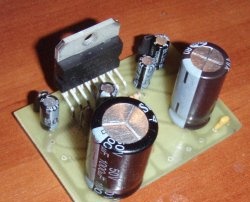
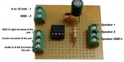
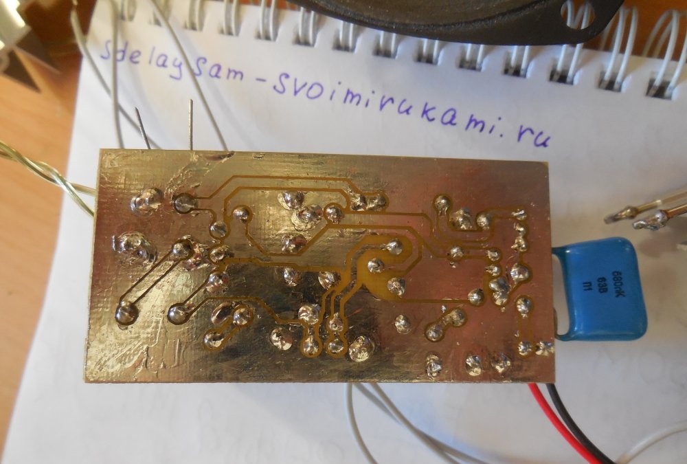
Amplifier board:
[17 Kb] (downloads: 514)
The board is made by the LUT method.
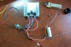
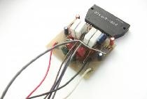
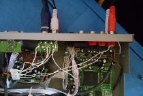
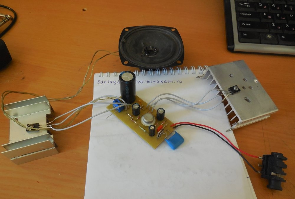
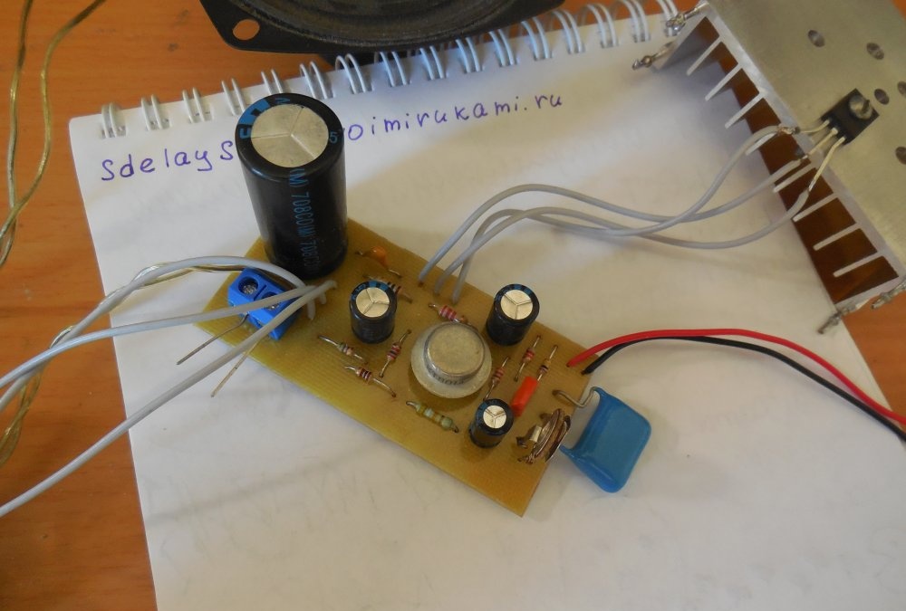
Amplifier assembled by me
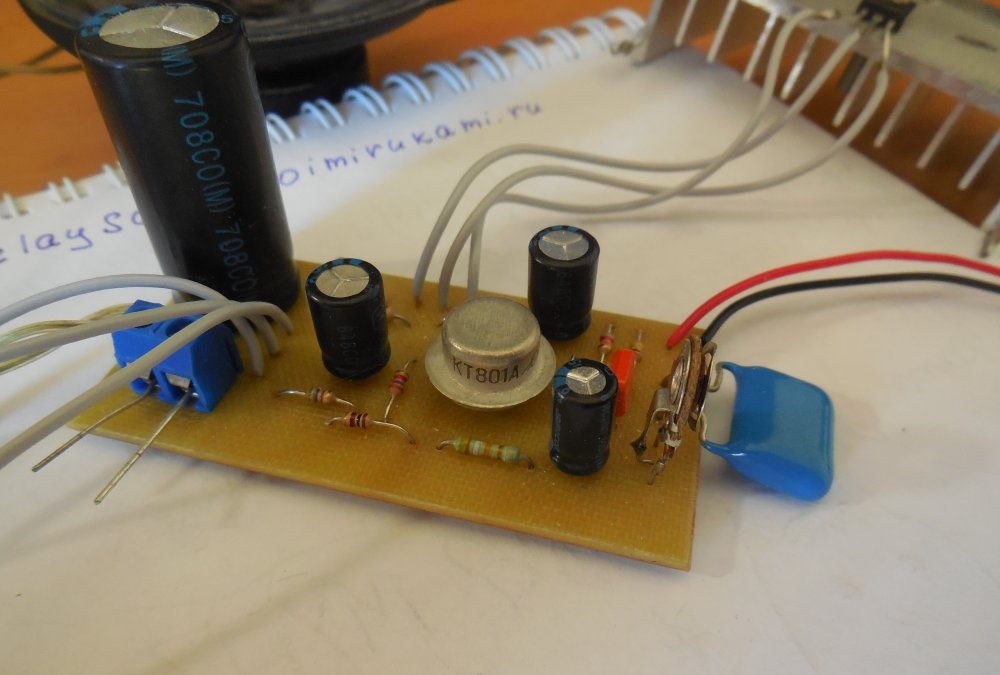
A few words about capacitors, input and output. The capacitance of the input capacitor in the circuit is indicated by 0.1 μF, but this capacity is not enough. As an input, you should put a film capacitor with a capacity of 0.68 - 1 μF, otherwise an undesirable cut of low frequencies is possible. The output capacitor C5 should be taken at a voltage no less than the supply voltage, and you should not be greedy with the capacity.
The advantage of the circuit of this amplifier is that it does not pose a danger to the speakers of the speaker system, because the speaker is connected through an isolation capacitor (C5), which means that when a constant voltage appears at the output, for example, when the amplifier fails, the speaker remains intact, after all, the capacitor will not miss a constant voltage.