Good afternoon, dear readers! Today we will build a simple power supply for low-power loads. Let me make a reservation right away: the power of the circuit can be increased, but more on that later.
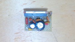
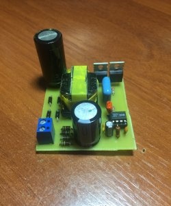
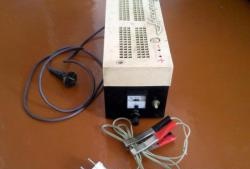
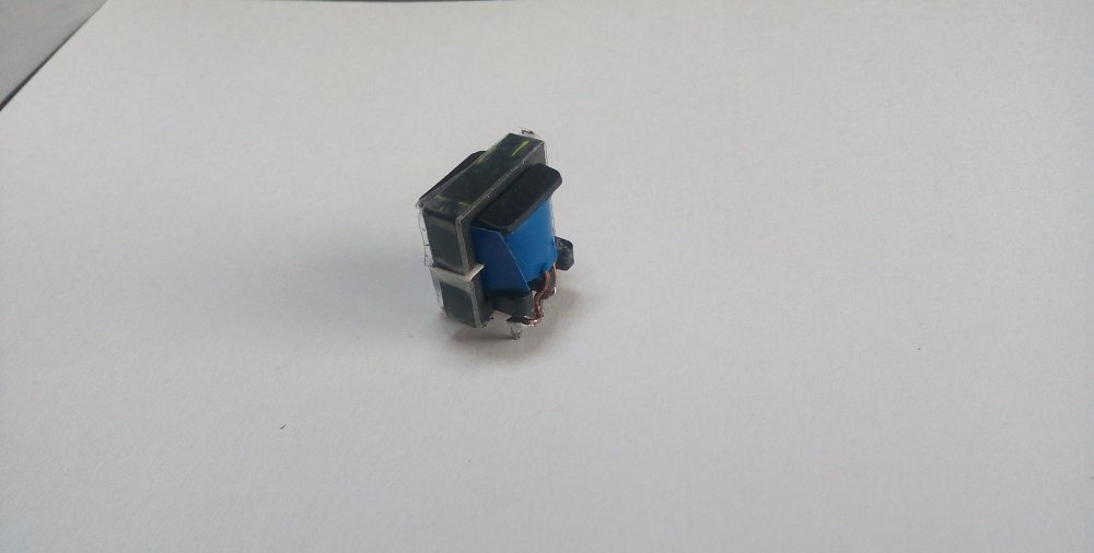
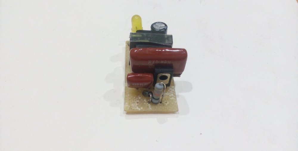
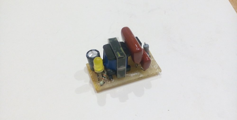
This is what the assembled structure looks like:
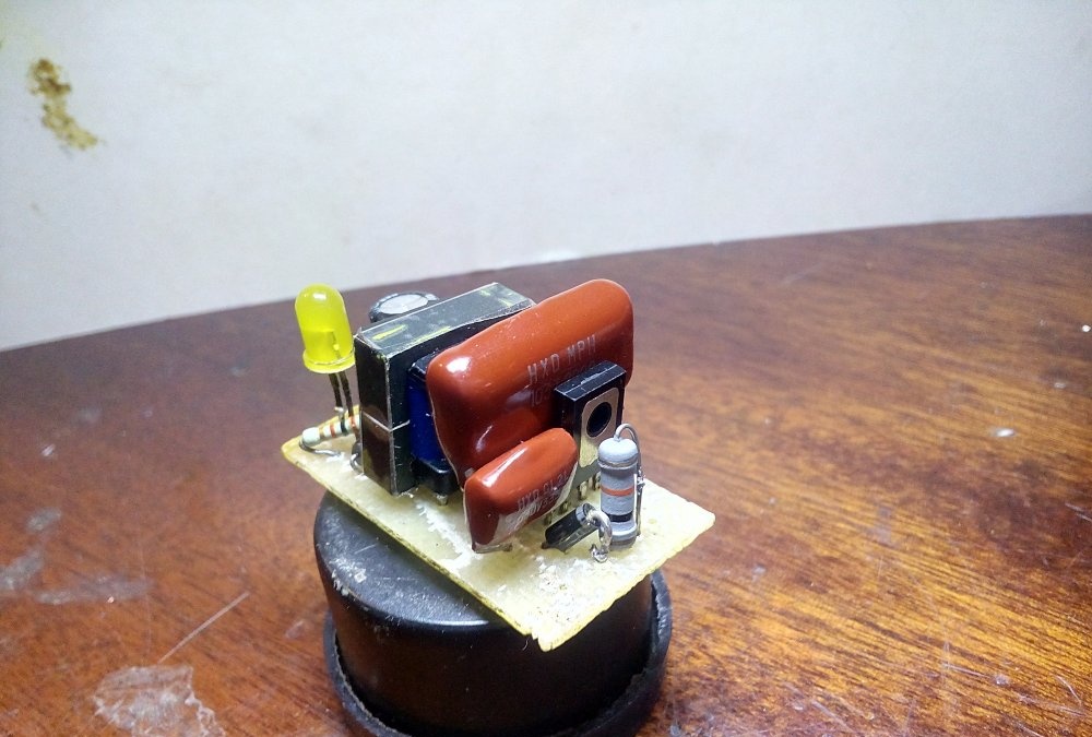
Quite compact.
Main characteristics:
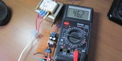
- Output voltage - 12 Volts;
- Power - 5 Watt;
- Wide range of supply voltages;
- Reliability.
Scheme
So, let's start with the device diagram. She is in front of you now.
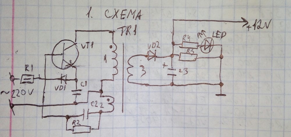
The high-voltage part is a single-cycle generator built on the basis of a single transistor.
Parts List:- VT1 – mje13001 (or more powerful mje13003);
- VD1 - 1N4007;
- VD2 – FR107;
- LED – Light-emitting diode any color (I took yellow);
- R1 – 15 kOhm, 0.5-1 Watt (in order to increase the power of the circuit, I took it to 10 kOhm);
- R2 – 300 kOhm;
- R3 – 2.2 kOhm;
- R4 – 1.5 kOhm;
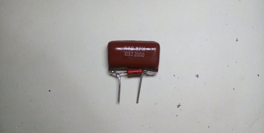
- C1 – 33 nF, 400 Volts;
- C2 – 10 nF, 1 kV (I didn’t have a kilovolt capacitor, so I took one for 2 kV);
- C3 – 100 µF.
Resistor R1 limits the output current, R2 discharges the capacitor after disconnecting the circuit from the network, R3 has the same role. Half-wave rectifiers are assembled on parts VD1 C1, VD2 C3.
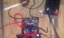
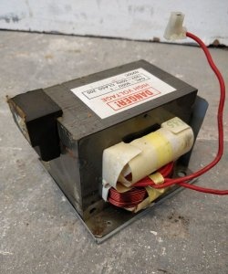
A suitable transformer can be found in old chargers. We carefully disassemble the core, wind up the old windings and begin winding new ones. The primary winding (also known as the collector winding) consists of 200 turns of wire with a diameter of 0.08 - 0.1 mm. You can wind it either manually or with a winding mechanism. The latter is useful because you can see how many turns there are already.
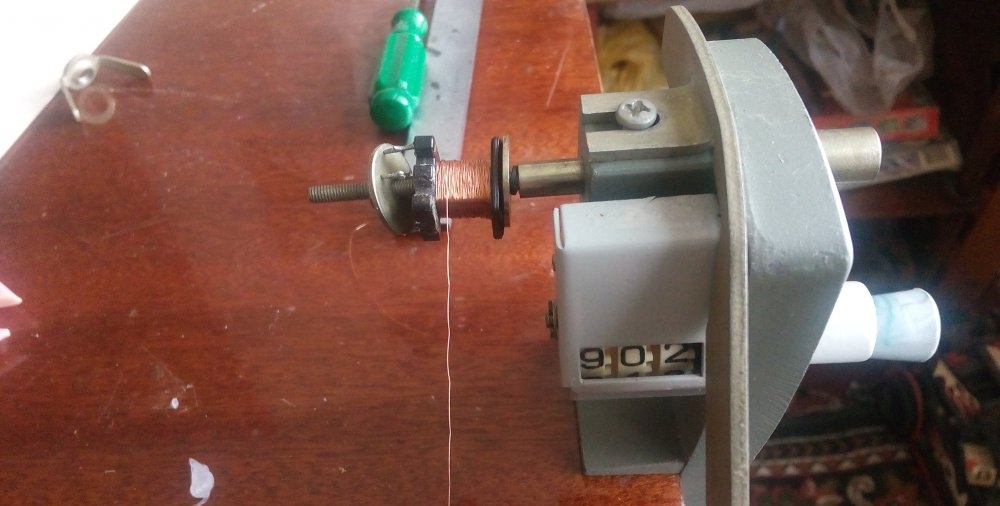
(In the photo the counter shows an incorrect value)
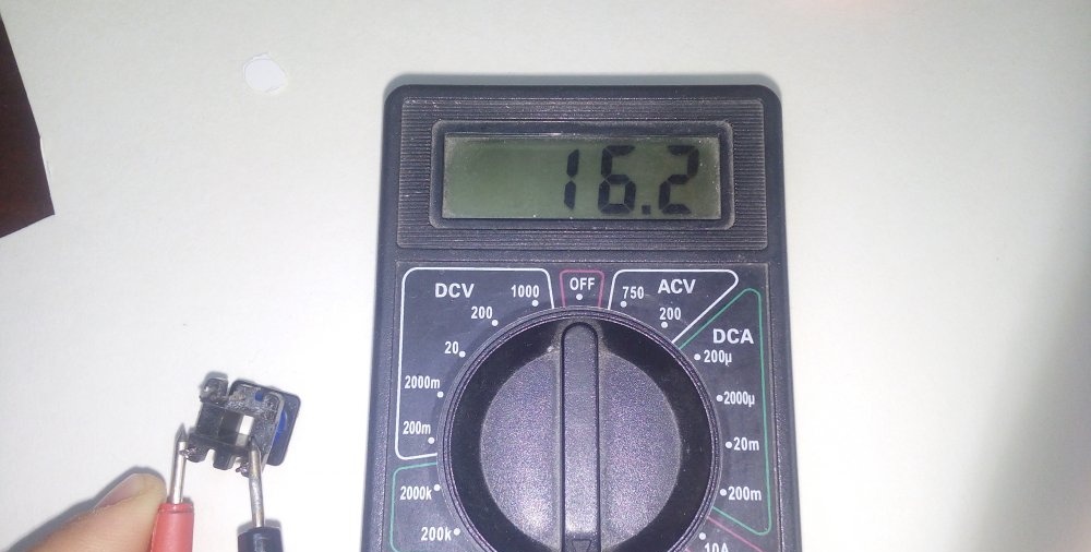
We ring the wound coil for breaks.
We put insulation, one layer is enough, and in the same direction we wind 10 turns of wire of the same diameter and insulate it.
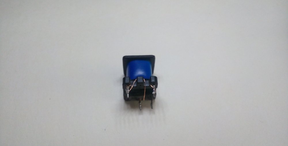
Now we take a thicker wire (0.5 mm) and wind the low-voltage winding with it. One turn is approximately equal to one Volt. I wound 14 turns to have a voltage reserve.
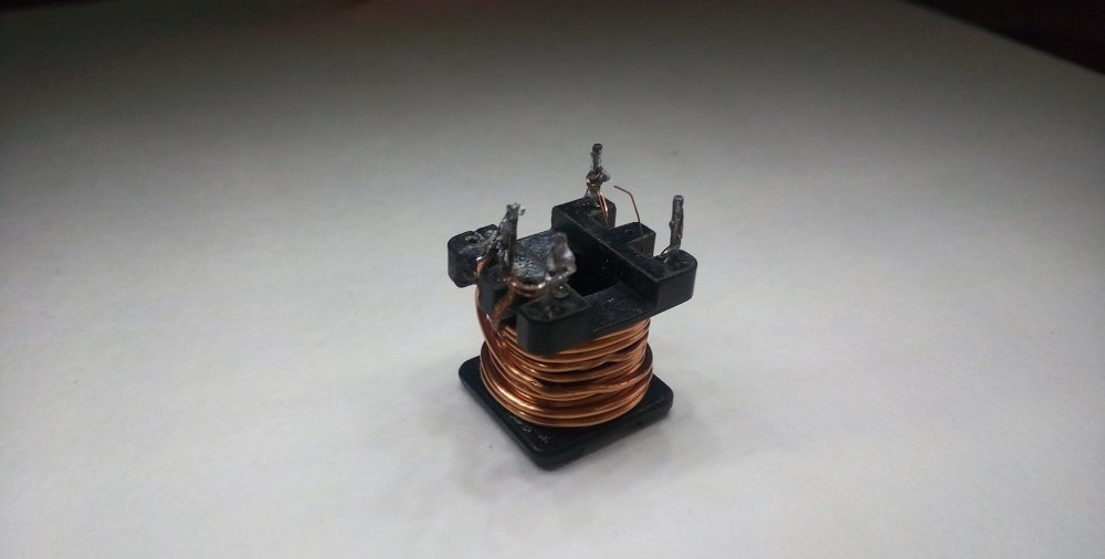
We also apply a layer of electrical tape to the secondary winding.
Since the generator is single-cycle, a piece of office paper should be placed between the parts of the core. We assemble the transformer and fix the core with tape. Ready!
Printed circuit board
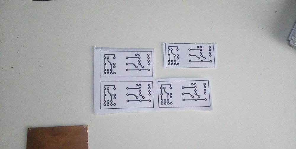
Download the board:
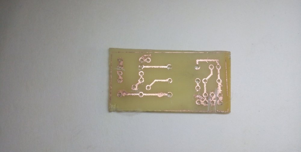
So, we’ve figured out the circuit and the role of its components, now let’s start making the printed circuit board. To do this, we need a PCB measuring 2x4 cm and the printed circuit board design itself.
Sand the copper part with fine-grained sandpaper, then degrease it with alcohol. Next, using the LUT method, we transfer the drawing to the board.
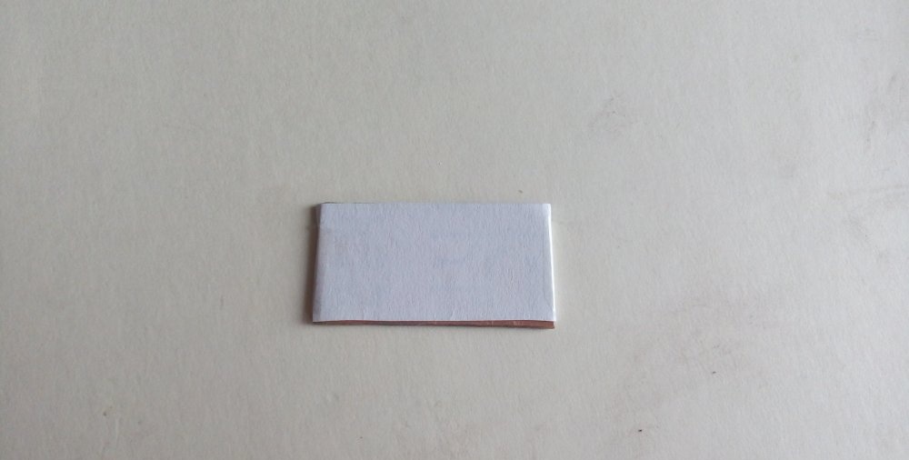
If something is not transferred, we finish painting it with varnish.
We etch in a solution of hydrogen peroxide. I recommend this particular etching method, as it is the safest, fastest and most accessible.
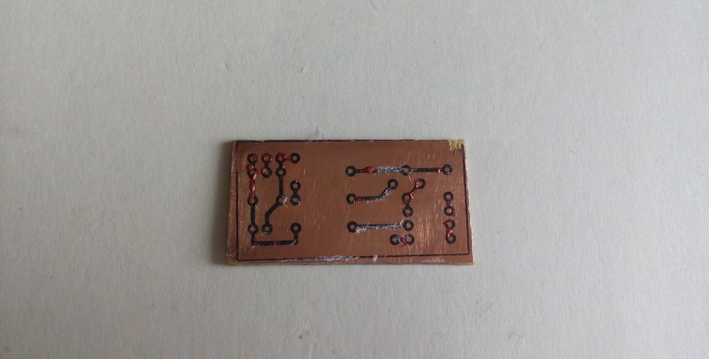
At the end of the etching process, we take out our board, rinse it with water, and wash off the toner and varnish with acetone.
Soldering the tracks
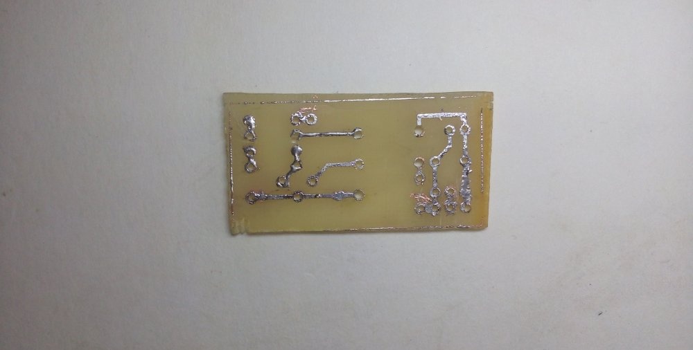
First we solder the VD2 diode into its place, do not forget about the polarity. The gray strip of the diode “looks” upward.
We solder resistor R2 to the legs of capacitor C2.
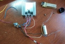
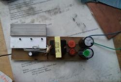
We place the remaining components on the board in accordance with the following photos:
Connection to the network
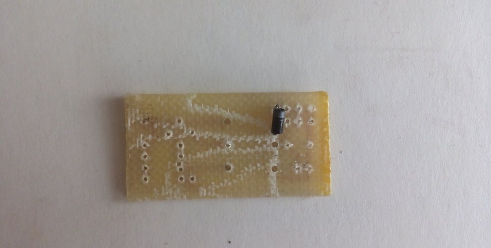
When you first plug in one of the power wires, you must connect a regular 40-60 Watt incandescent lamp. This will protect your network from the consequences of a possible short circuit in the circuit. If the lamp does not light up during operation, then everything is normal and you can turn it off. Otherwise, find and fix the problem. Often this is excess solder on the back of the board, which can short out the traces.
Conclusion
The reliability of the circuit lies in the fact that if there is a short circuit at the output of the circuit, all energy is dissipated in the form of heat on resistor R1.
The output power depends on the value of resistor R1, the dimensions of the transformer and the diameter of the secondary winding, the voltage depends on the number of turns.
The circuit does not need adjustment.
And this concludes my article. Good luck with your repetition everyone!