Scheme
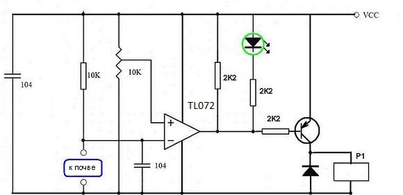
I propose for assembly a diagram of a simple and proven soil moisture sensor, a diagram of which is shown below:
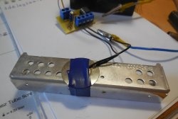
Two metal rods are lowered into the kidney of the pot, which can be done, for example, by straightening the paper clip. They need to be stuck in the ground at a distance of about 2-3 centimeters from each other. When the soil is dry, it conducts poorly electric current, the resistance between the rods is very high. When the soil is wet - its electrical conductivity increases significantly and the resistance between the rods decreases, it is this phenomenon that underlies the operation of the circuit.
The 10 kΩ resistor and the soil section between the rods form a voltage divider, the output of which is connected to the inverting input of the operational amplifier. Those. The voltage on it depends only on how moist the soil is. If you place the sensor in moist soil, then the voltage at the input of the op-amp will be approximately 2-3 volts. As the earth dries, this voltage will increase and will reach 9-10 volts with completely dry earth (specific voltage values depend on the type of soil). The voltage at the non-inverting input of the op-amp is set manually by a variable resistor (10 kOhm in the circuit, its value can be changed within 10-100 kOhm) in the range from 0 to 12 volts. Using this variable resistor, the sensor threshold is set. The operational amplifier in this circuit operates as a comparator, i.e. It compares the voltages at the inverting and non-inverting inputs. As soon as the voltage from the inverting input exceeds the voltage from the non-inverting one, minus power will appear at the output of the op-amp, the LED will turn on and the transistor will open. The transistor, in turn, activates a relay that controls the water pump or electric valve. Water will begin to flow into the pot, the earth will become moist again, its electrical conductivity will increase, and the circuit will shut off the water supply.
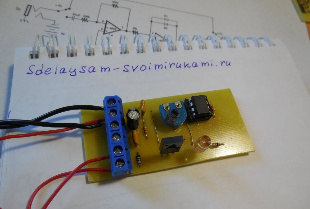
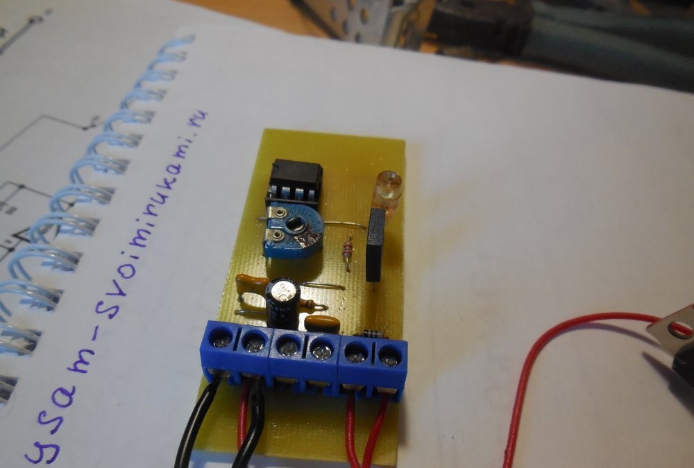
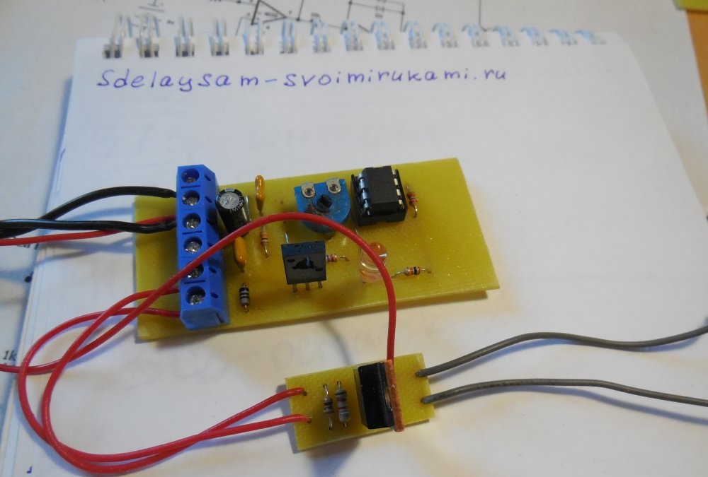
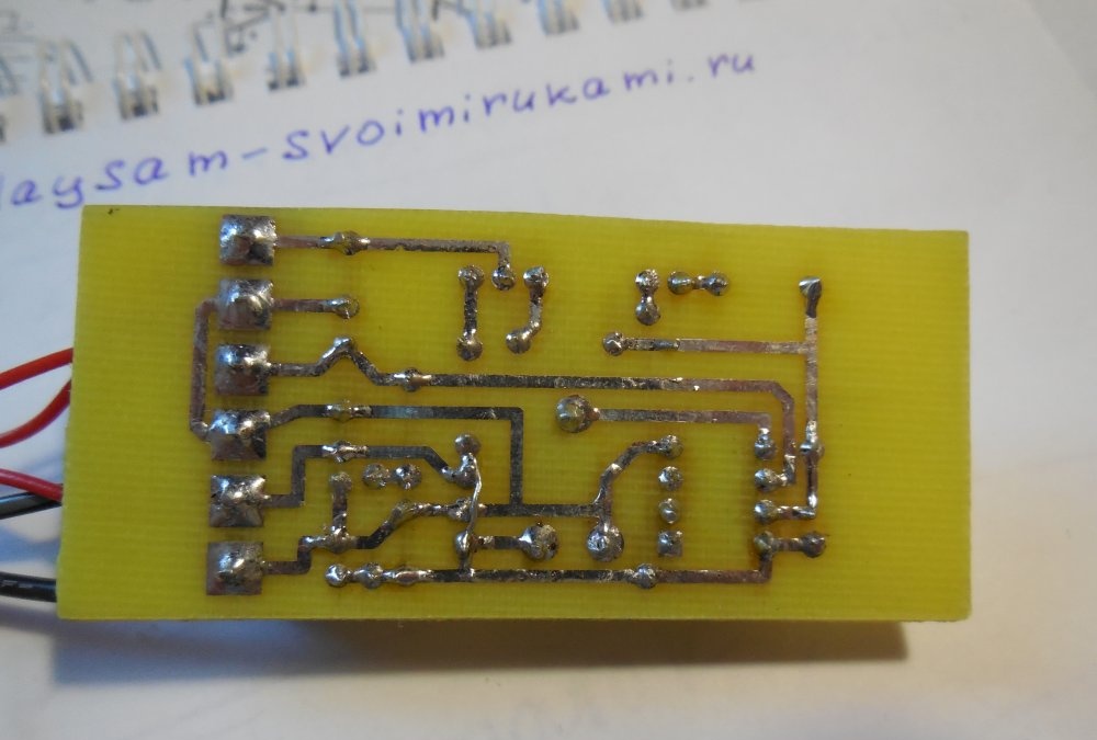
The printed circuit board proposed for the article is designed to use a dual operational amplifier, for example, TL072, RC4558, NE5532 or other analogs, one half of which is not used. The transistor in the circuit uses low or medium power and PNP structures, for example, KT814 can be used. Its task is to turn the relay on and off, and instead of the relay, you can use the key on the field effect transistor, as I did. The supply voltage of the circuit is 12 volts.
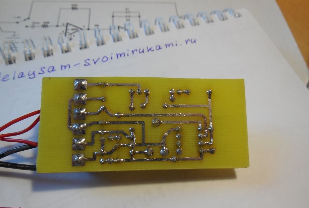
Download board:
[6.96 Kb] (downloads: 323)
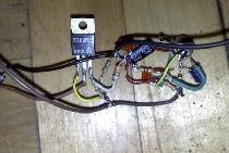
Assembling a soil moisture sensor
It may happen that when the soil dries, the relay does not turn on clearly, but first it starts to snap quickly, and only after that it is installed in the open state. This suggests that the wires from the board to the pot with the plant pick up network interference, which adversely affects the operation of the circuit. In this case, it does not hurt to replace the wires with shielded ones and put an electrolytic capacitor with a capacity of 4.7 - 10 microfarads parallel to the soil, in addition to the capacitance of 100 nF indicated in the diagram.
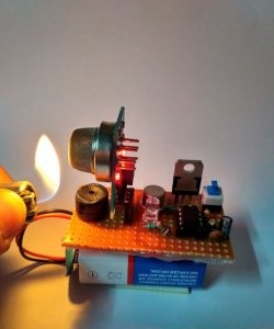
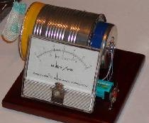
I really liked the operation of the circuit, I recommend it for repetition. Photo of the device I collected: