Scheme
The diagram of this device is presented below:

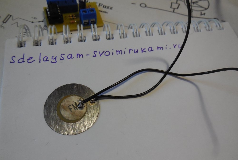
A sensitive element of the circuit is a piezodynamic, an element that generates an electric current at the slightest deformation. It will be he who will record the blow and send a signal to the input of the operational amplifier. You can get such a piezodynamic from some squeaking toy, an electronic clock with an alarm clock, a calculator, or just buy it in a store. It looks like this:
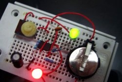
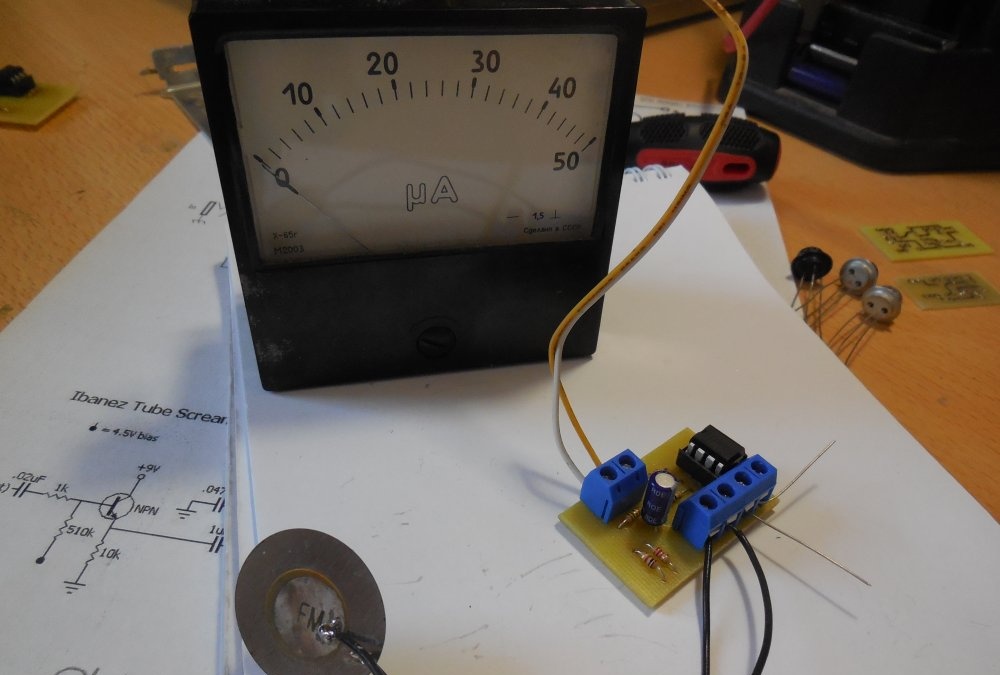
It is enough to touch or strike him a little, as the needle of the microammeter will jump up. A tuning resistor should be installed in series with the microammeter to adjust its sensitivity. The circuit uses a single operational amplifier LM358, you can use its analogs, for example, TL071. The minimum supply voltage depends on the choice of the operational amplifier, if you use LM358, then the minimum supply voltage will be 3 volts, if you take TL072, then the circuit will work at least 7 volts. Do not increase the supply voltage of more than 16 volts.
The low-resistance resistor R4 in the circuit sets the sensitivity. The lower its resistance, the more responsive the circuit becomes even to small strokes. You should not lower its resistance below 0.33 ohms, the sensitivity of the circuit is enough with your head. Instead of an arrowhead, you can put an LED, then it will flash in time with the beats.
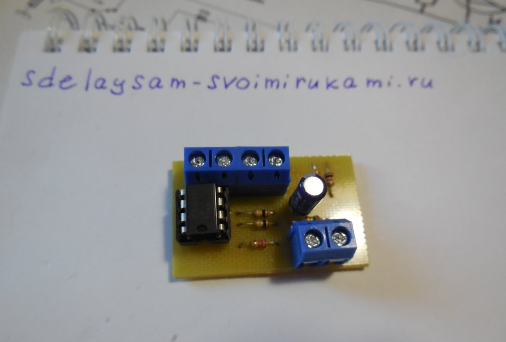
A few words about connecting piezodynamics. It consists of two plates, one of which is larger than the first in diameter. The central plate, which is smaller in diameter, should be connected to terminal 3 of the microcircuit, and the large plate, respectively, to the adjacent contact on the board. The printed circuit board contains two contacts for connecting power, two contacts for connecting piezodynamics and two for output, i.e. connecting the switch head or LED. It is most convenient to install screw terminal blocks to connect and disconnect wires from the board without using a soldering iron.
Manufacture
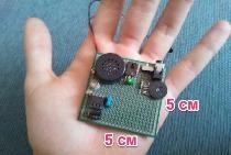
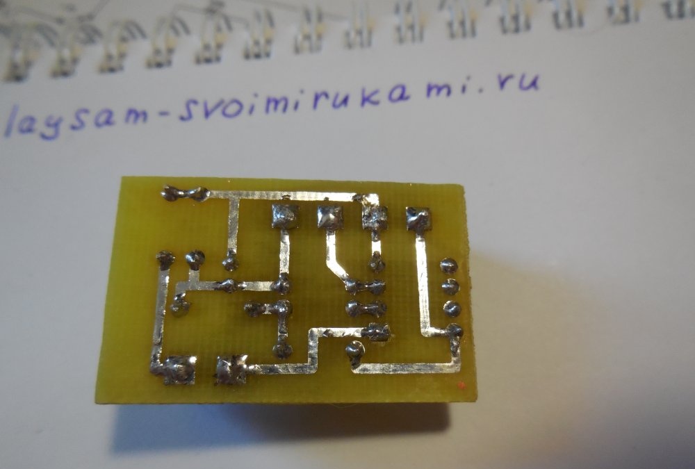
The printed circuit board is made by the LUT method and it looks like this:

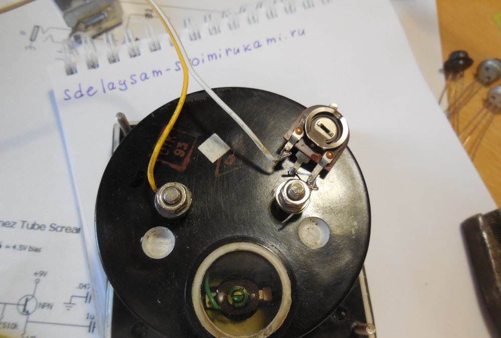
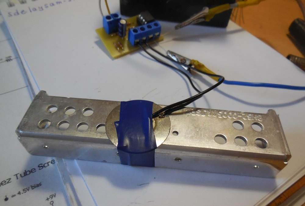
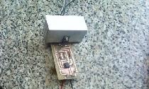
The piezodynamic should be fixed on a massive solid object that will transmit vibrations. You can fix it on the front door, and as soon as someone knocks on it, the circuit will register a knock and notify the owner.
Watch the video of work
The principle of operation is clearly shown in the video: