However, switching a powerful load is possible not only with a relay. Recently, powerful field-effect transistors have become widespread. One of their main purposes is to work in key mode, i.e. the transistor is either closed or fully open when the resistance of the Stoke - Source transition is practically zero. You can open the field effect transistor by applying voltage to the gate relative to its source. You can compare the operation of the key on the field effect transistor with the operation of the relay - they applied voltage to the gate, the transistor opened, the circuit closed. They removed the voltage from the shutter - the circuit opened, the load is de-energized.
At the same time, the key on the field-effect transistor has some advantages over the relay, such as:
- Great durability. Quite often, relays fail due to the presence of mechanically moving parts, while the transistor, under the right operating conditions, has a much longer service life.
- Profitability. The relay coil consumes current, and sometimes it is very significant. The gate of the transistor consumes current only at the moment of supplying voltage to it, then it practically does not consume current.
- No clicks when switching.
Scheme
The key diagram for the field effect transistor is presented below:
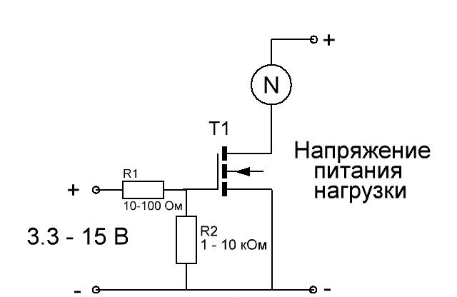
The resistor R1 in it is current-limiting, it is needed in order to reduce the current consumed by the gate at the time of opening, without it the transistor can fail. The value of this resistor can be easily changed over a wide range, from 10 to 100 Ohms, this will not affect the operation of the circuit.
Resistor R2 pulls the gate to the source, thereby equalizing their potentials when no voltage is applied to the gate. Without it, the shutter will remain "hanging in the air" and the transistor will not be able to close guaranteed. The value of this resistor can also be changed over a wide range - from 1 to 10 kOhm.
Transistor T1 is an N-channel field effect transistor. It must be selected based on the power consumed by the load and the magnitude of the control voltage. If it is less than 7 volts, you should take the so-called "logical" field effect transistor, which reliably opens from a voltage of 3.3 - 5 volts. They can be found on computer motherboards. If the control voltage lies within 7-15 volts, you can take a "conventional" field effect transistor, for example, IRF630, IRF730, IRF540 or any other similar. In this case, attention should be paid to such a characteristic as open channel resistance. Transistors are not perfect, and even in the open state, the resistance of the Stoke - Source transition is not equal to zero. Most often, it amounts to hundredths of an Ohm, which is absolutely not critical when switching a load of low power, but very significantly at high currents. Therefore, in order to reduce the voltage drop across the transistor and, accordingly, reduce its heating, it is necessary to choose a transistor with the lowest open channel resistance.
“N” in the diagram is some kind of load.
The disadvantage of the key on the transistor is that it can only work in DC circuits, because the current goes only from the Stock to the Source.
Production of a key on a field effect transistor
Such a simple circuit can also be assembled by wall mounting, but I decided to make a miniature printed circuit board using laser-iron technology (LUT). The procedure is as follows:
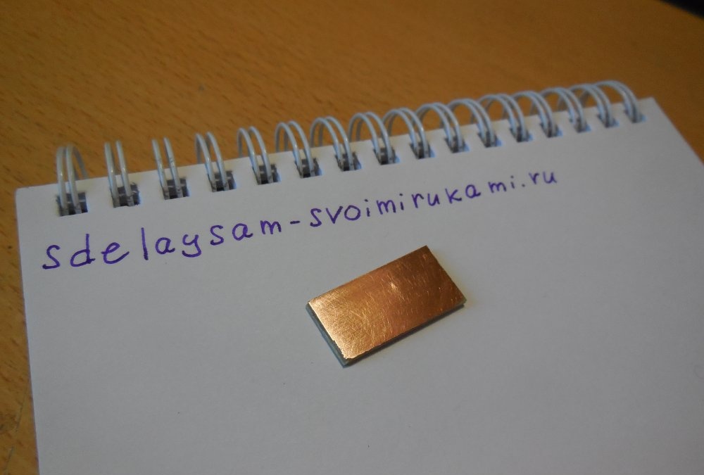
1) We cut out a piece of PCB suitable for the dimensions of the printed circuit board, clean it with fine sandpaper and degrease it with alcohol or solvent.
2) On a special thermal transfer paper we print a printed circuit board. You can use glossy magazine paper or tracing paper. The toner density on the printer should be set to the maximum.
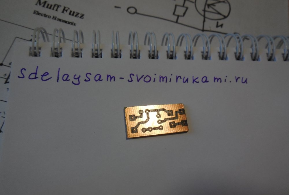
3) Transfer the pattern from paper to textolite using an iron. In this case, it should be controlled so that the piece of paper with the pattern does not shift relative to the PCB. The heating time depends on the temperature of the iron and lies within 30 - 90 seconds.
4) As a result, a picture of tracks in mirror image appears on the textolite. If the toner in places does not adhere well to the future board, you can fix the blemishes with the help of women's nail polish.
5) Next, we put the textolite etched. There are many ways to make an etching solution; I use a mixture of citric acid, salt and hydrogen peroxide.
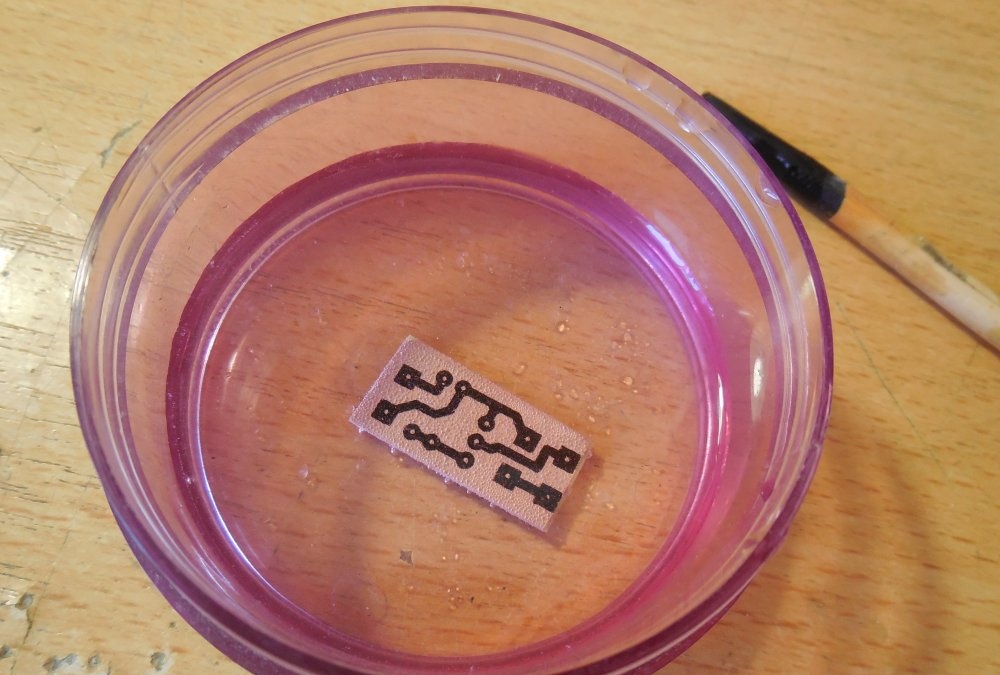
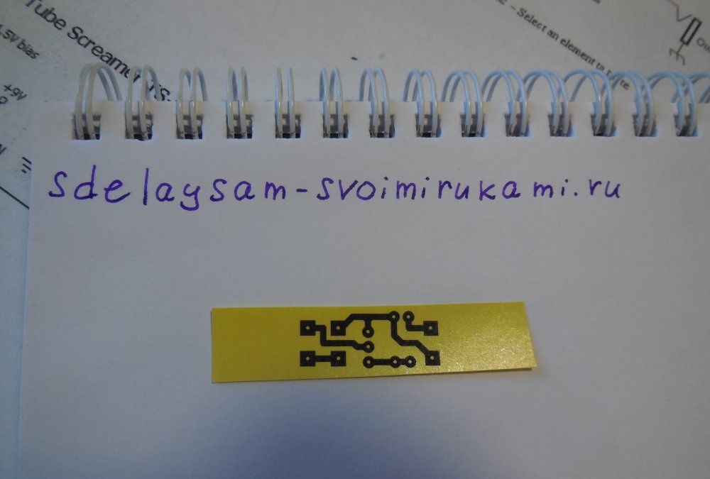
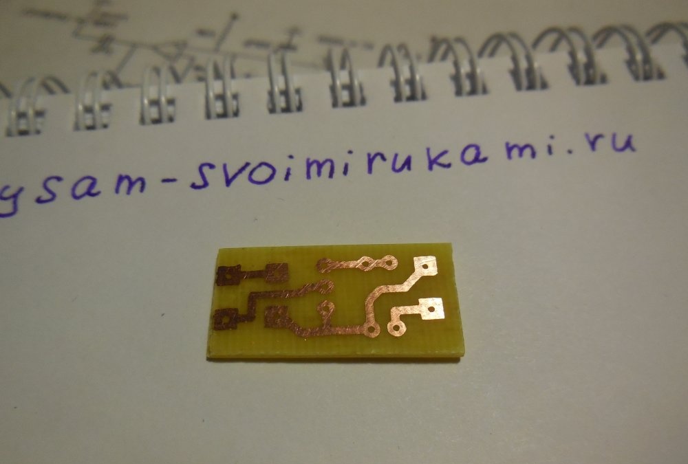
After etching, the board takes the following form:
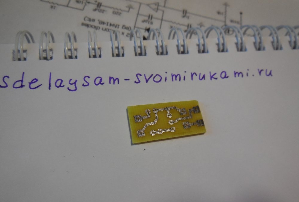
6) Then it is necessary to remove the toner from the PCB, the easiest way to do this is to use nail polish remover. You can use acetone and other similar solvents, I used an oil solvent.
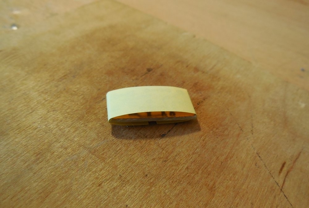
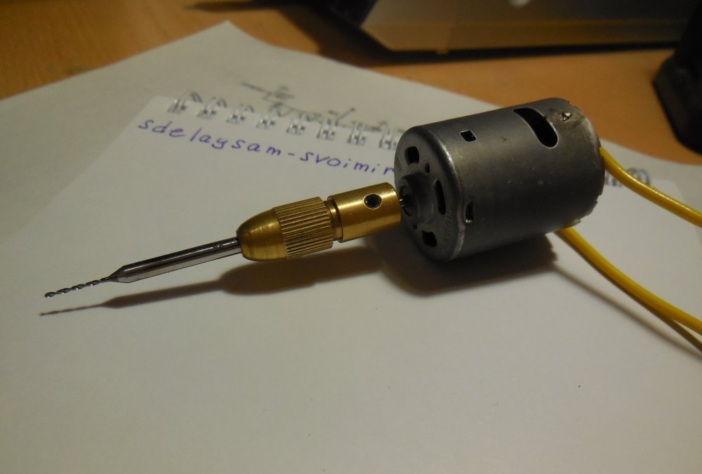
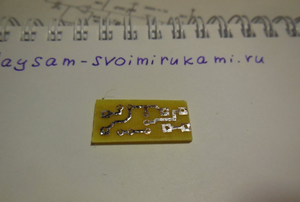
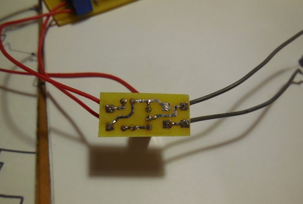
7) The case is small - now it remains to drill holes in the right places and tin board. After that, it takes on this form:
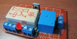
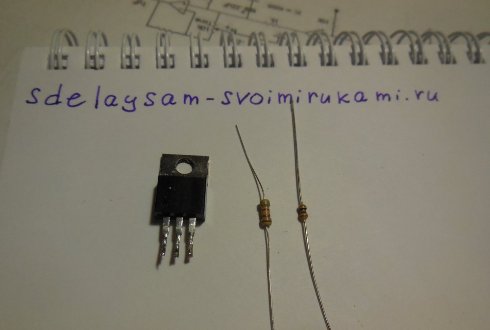
The board is ready to solder parts into it. Only two resistors and a transistor are required.
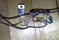
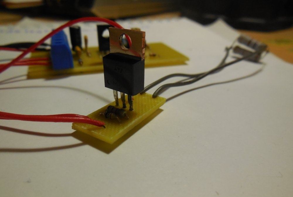
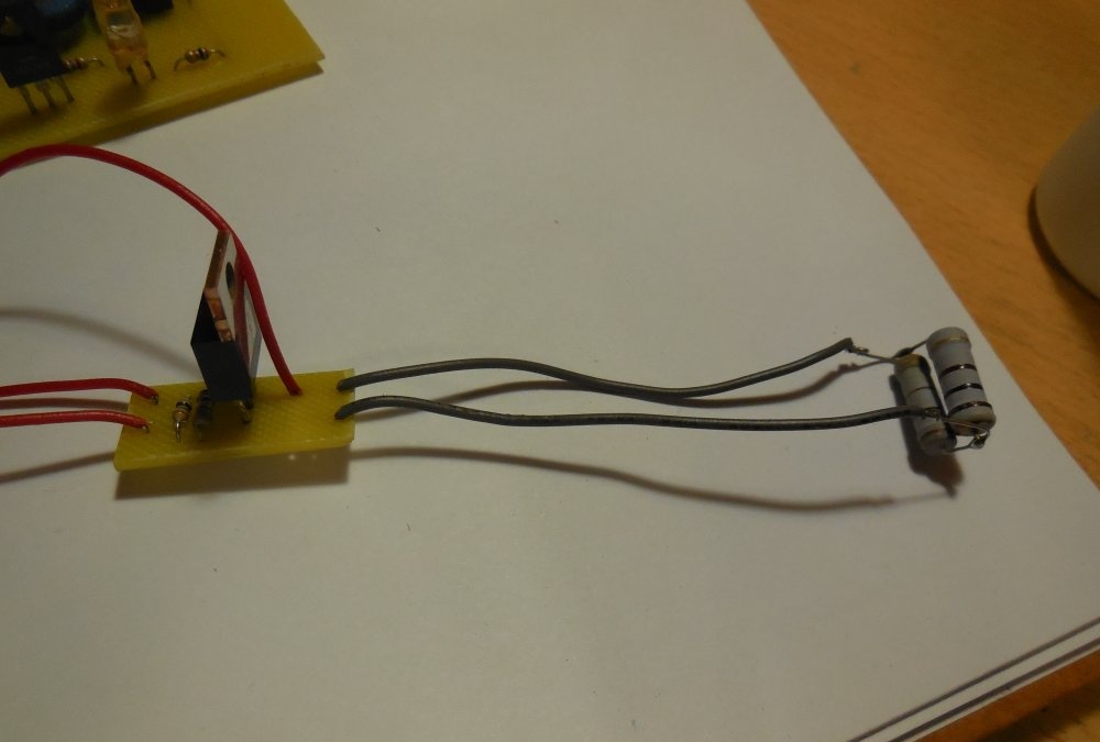
There are two contacts on the board for supplying control voltage to them, two contacts for connecting the source supplying the load, and two contacts for connecting the load itself. A board with soldered parts looks like this:

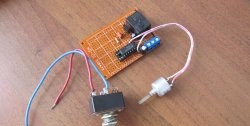
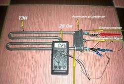
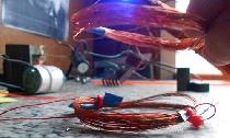
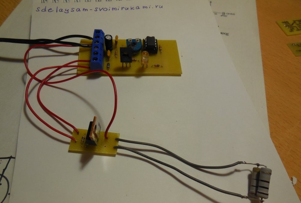
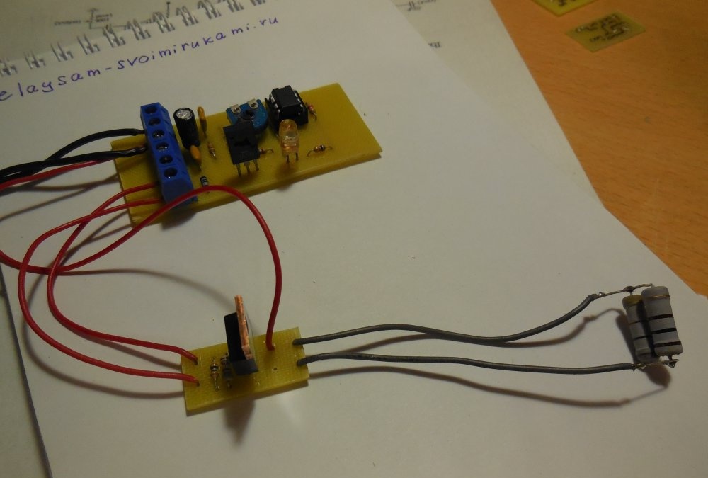
As a load for checking the operation of the circuit, I took two powerful 100 Ohm resistors connected in parallel.
I plan to use the device in conjunction with a humidity sensor (board in the background). It is from him that the control voltage of 12 volts comes to the key circuit. Tests have shown that the transistor switch works great by supplying voltage to the load. The voltage drop across the transistor was 0.07 volts, which is not critical at all in this case. Heating of the transistor is not observed even with constant operation of the circuit. Successful assembly!
Download board and circuit:
[4.93 Kb] (downloads: 751)