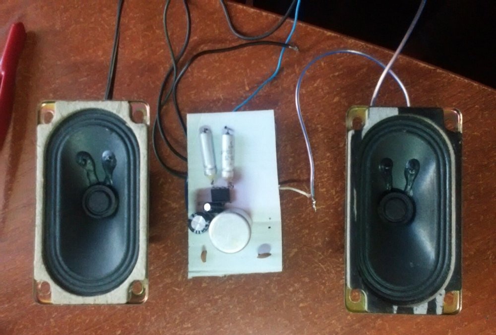
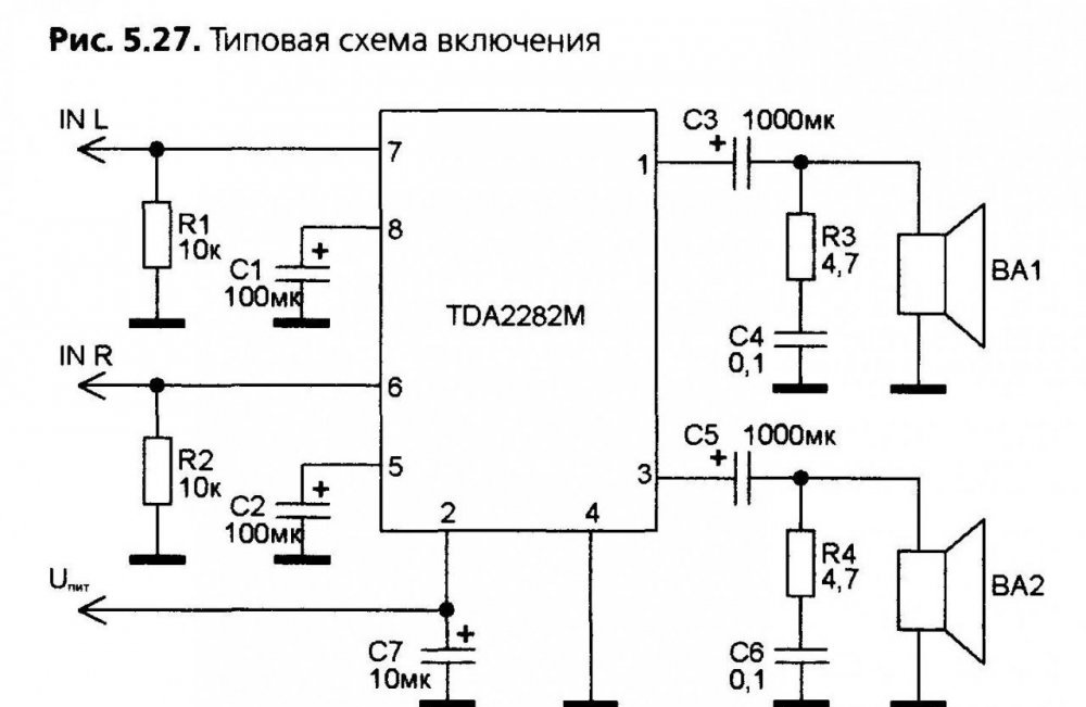
Hello friends. Today I will tell you how to make a small power amplifier on a tda2822m chip. Here is the circuit I found in the datasheet of the chip. We will make a stereo amplifier, that is, there will be two speakers - the right and left channels.
Amplifier circuit
We will need:
- Chip TDA2822m.
- 4.7 ohm resistor (2 pcs.).
- Resistor 10 Kom (2 pcs.).
- 100 uF capacitor (2 pcs.).
- Capacitor 10 MkF.
- Capacitor 1000 MkF (2 pcs.).
- 0.1 MkF capacitor (2 pcs.).
- Speaker (about 4 ohms and 3 watts) (2 pcs.).
Amplifier assembly
We will assemble the circuit on something in between the hinged installation and the printed circuit board. A piece of cardboard will serve as a board, we will attach all the details to it.
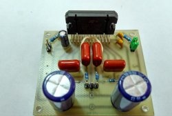
For radio parts, use a pin to make holes for the legs. In most cases, the legs will be in the role of the tracks with which we will separate the entire circuit. The first thing we insert is the microcircuit itself, then to the very first leg we solder the plus leg of the capacitor at 1000 microfarads.
 [center]
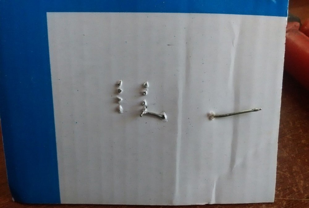
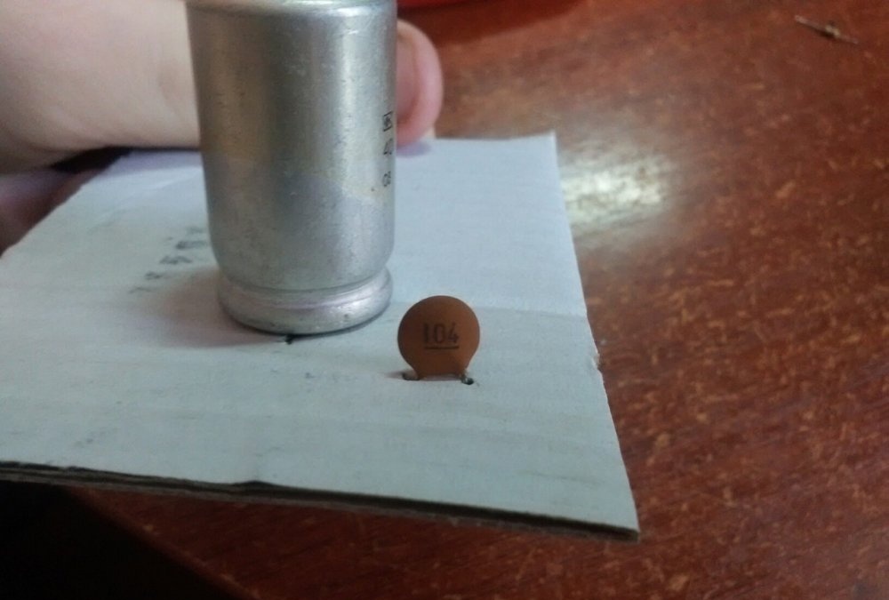
Next, solder a 4.7 Ohm resistor to the minus leg, and a 0.1 μF capacitor to it (the capacitor has a marking 104). We also solder the wire to the minus foot of the 1000 μF capacitor, one of the speakers will go to it.

We do the same with the third leg of the microcircuit.
Next, solder to the second leg of the microcircuit the positive leg of the capacitor at 10 uF and the wire, which will be the plus of the power supply.
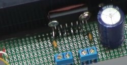
To the fifth and eighth legs of the microcircuit we solder the plus legs of the capacitors at 100 microfarads.
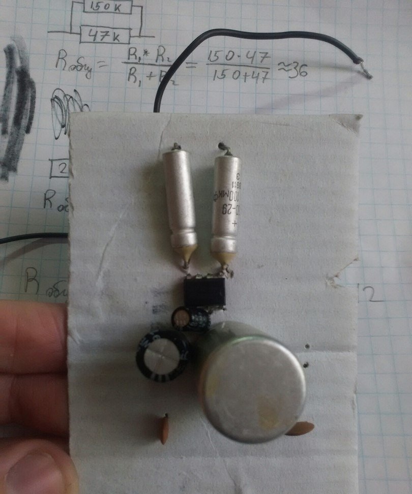
We solder two wires to the sixth and seventh legs of the microcircuit - these are the right and left channels (the sixth is right, the seventh is left). We also solder two resistors at 10 com. Here I have a problem. There was only one resistor per 10 com. Going to the store for one resistor is unreasonable, so I had to remember some of the physics lessons. Namely, how to calculate the resistance when connecting two resistors in parallel. This is what the formula looks like:
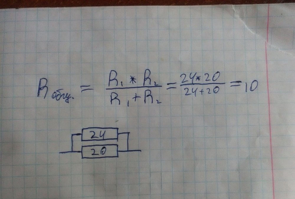
But this formula only works with two resistors, if their formula does not fit anymore. I found 20 and 24 resistors, these are some old Soviet resistors.

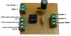
On this, almost everything is ready. It remains to deal with the land, it will be a minus of food. All remaining legs from capacitors to 100; 10; 0.1 microfarads, as well as from resistors at 10 kΩ, must be connected in one beam. I connected all the earth on a 100 μF capacitor leg, in some places I had to connect with wires. Earth, also 4 foot microchips.

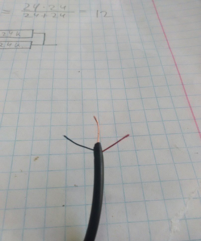
Also, the ground will be the minuses of the speakers. Now solder the 3.5 mm jack. The copper wire is earth, red is the right channel soldered to the sixth leg of the microcircuit (to the wire that was removed earlier), blue is the left channel, soldered to the seventh leg.
Plus, each speaker is connected to the minus leg of 1000 μF capacitors. Cons of the speakers are soldered to a common ground. The plus of the power supply is the wire from the second leg of the microcircuit, as I said earlier, the minus of the power supply is ground. This completes the manufacture of the circuit. We cut the cardboard, if the compactness of the circuit is important, then the cardboard should initially be taken smaller, since there are few elements on the circuit.