Do it yourself
Life hacks, master classes, useful tips, recipes.
home » Electronics » Simple circuits » The simplest scheme for automatic water level control

A do-it-yourself device using a single transistor can be made by almost anyone who wants it and makes a little effort to purchase very inexpensive and not numerous components and solder them into a circuit. It is used to automatically replenish water in supply containers at home, in the country and wherever water is present, without restrictions. And there are a lot of such places. First, let's look at the diagram of this device. It just couldn't be simpler.

Control the water level automatically using a simple electronic water level control circuit.

The entire water level control circuit consists of several simple parts, and if assembled without errors from good parts, it does not need adjustment and will immediately work as planned. A similar scheme has been working for me without failures for almost three years, and I am very pleased with it.

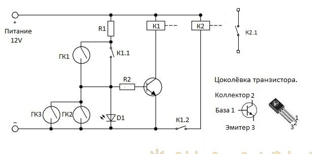
Automatic water level control circuit
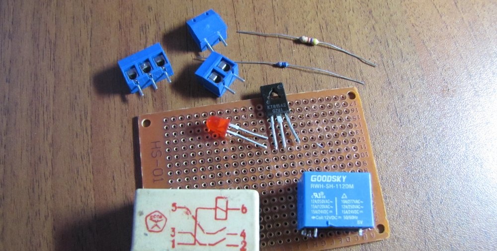
Parts List:

  • You can use any of these transistors: KT815A or B. TIP29A. TIP61A. BD139. BD167. BD815.
  • GK1 – lower level reed switch.
  • GK2 – upper level reed switch.
  • GK3 – emergency level reed switch.
  • D1 – any red Light-emitting diode.
  • R1 – resistor 3Kom 0.25 watts.
  • R2 – resistor 300 Ohm 0.125 watt.
  • K1 – any 12 volt relay with two pairs of normally open contacts.
  • K2 – any 12 volt relay with one pair of normally open contacts.
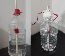
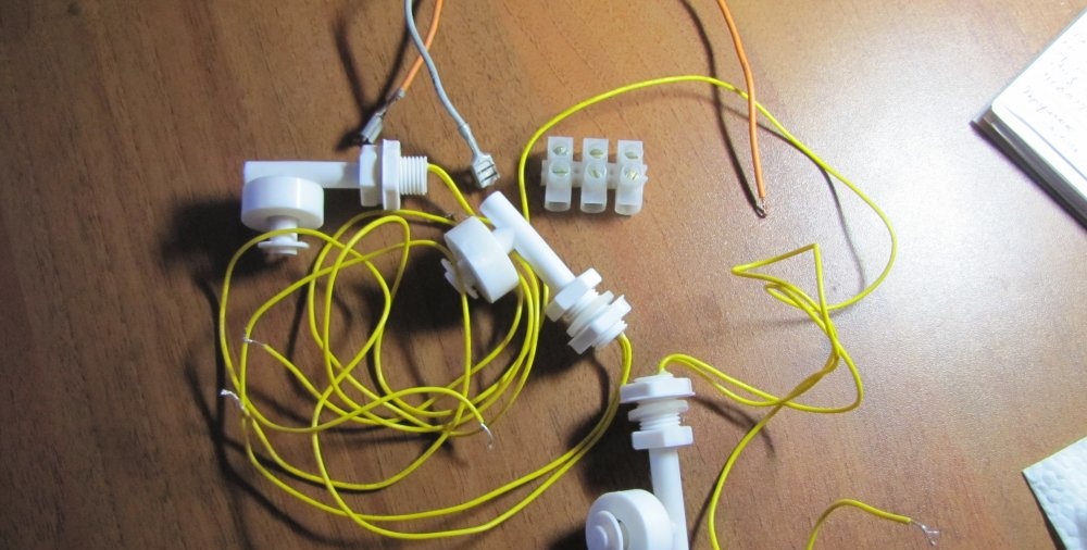
  • I used float reed contacts as signal sources for replenishing water in the container. The diagram is designated as GK1, GK2 and GK3. Made in China, but of very decent quality. I can't say a single bad word. In the container where they stand, I treat the water with ozone and over the years of work there has not been the slightest damage to them. Ozone is an extremely aggressive chemical element and it dissolves many plastics completely without any residue.

Now let's look at the operation of the circuit in automatic mode.

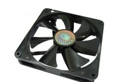
When power is supplied to the circuit, the lower level float GK1 is activated and power is supplied to the base of the transistor through its contact and resistors R1 and R2. The transistor opens and thereby supplies power to the relay coil K1. The relay turns on and with its contact K1.1 blocks GK1 (lower level), and with contact K1.2 it supplies power to the coil of relay K2, which is an actuator and turns on the actuator with its contact K2.1. The actuator can be a water pump or an electric valve that supplies water to the container.

The water is replenished and when it exceeds the lower level, GK1 turns off, thereby preparing the next cycle of work. Having reached the upper level, the water will raise the float and turn on GK2 (upper level), thereby closing the chain through R1, K1.1, GK2. The power to the base of the transistor will be interrupted, and it will close, turning off relay K1, which with its contacts will open K1.1 and turn off relay K2.The relay, in turn, turns off the actuator. The circuit is prepared for a new cycle of work. GK3 is an emergency level float and serves as insurance if the upper level float suddenly does not work. Diode D1 is an indicator that the device is operating in water filling mode.

Now let's start making this very useful device.

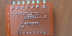
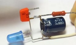
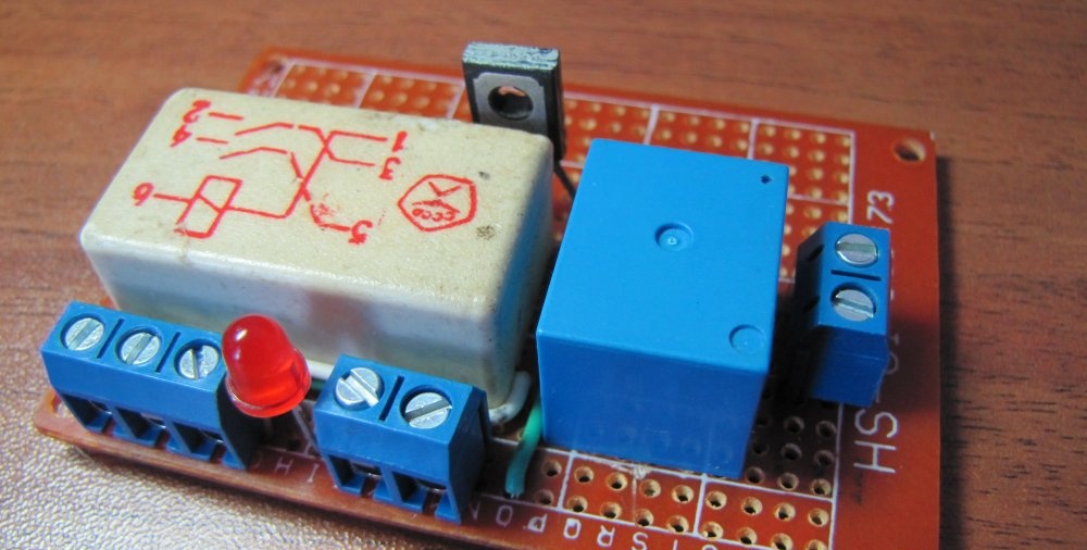
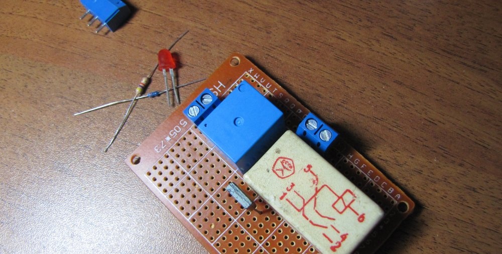
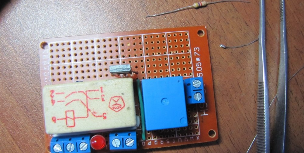
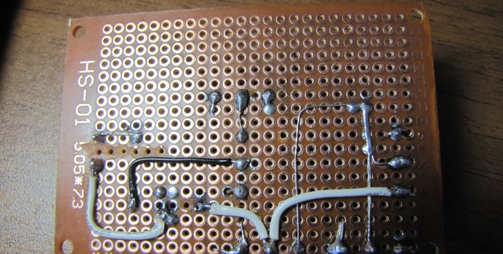
We place the parts on the board.

We place all the parts on a breadboard so as not to make a printed one. When placing parts, you need to take into account to solder as few jumpers as possible. It is necessary to make maximum use of the conductors of the elements themselves for installation.
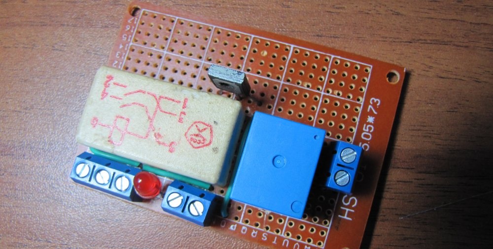
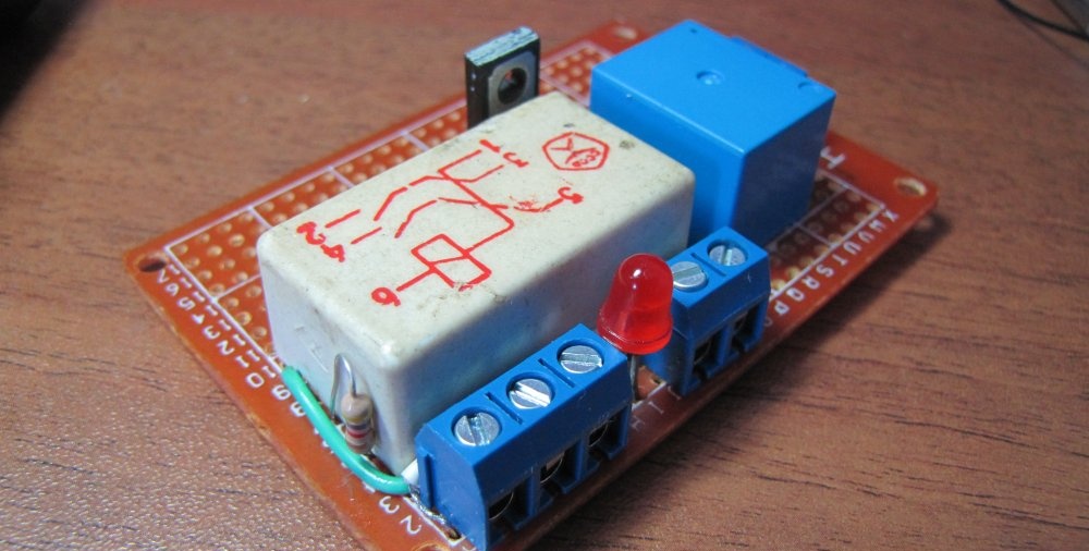
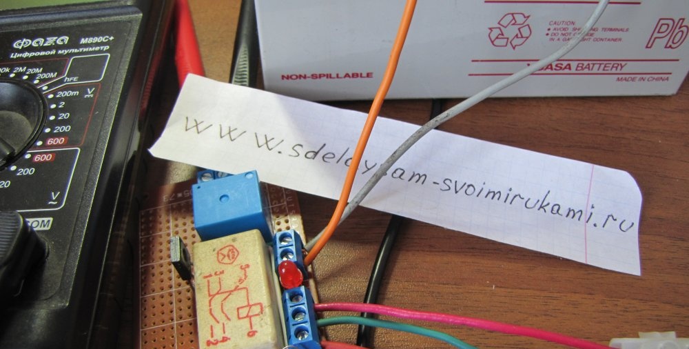
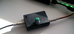
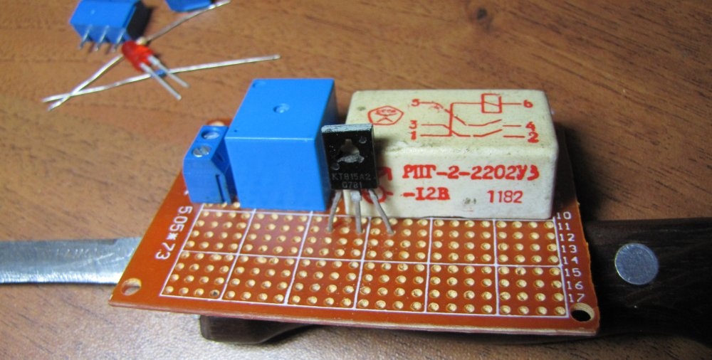
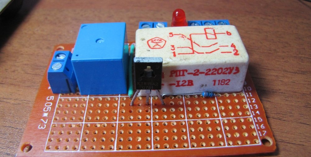
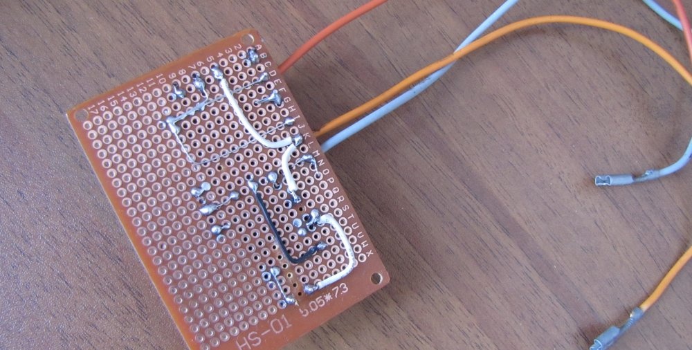
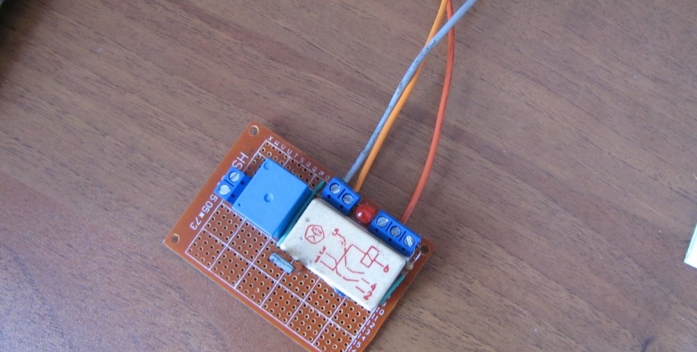
Final look.

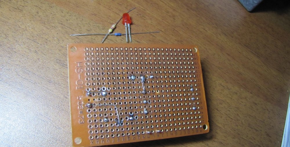
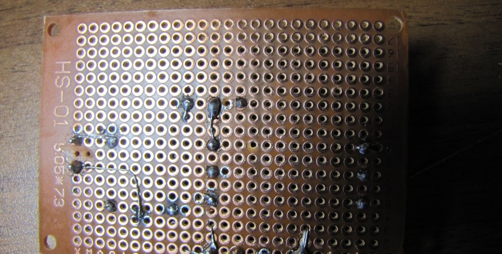
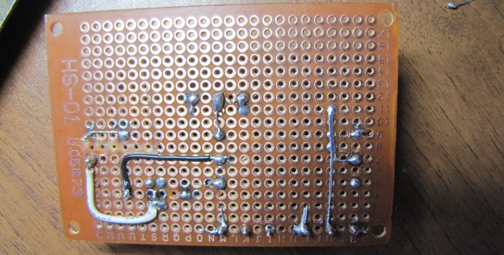
The water level control circuit is sealed.

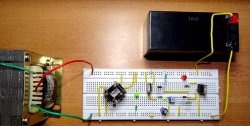
The circuit is ready for testing.

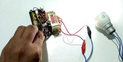
We connect it to the battery and simulate the operation of the floats.

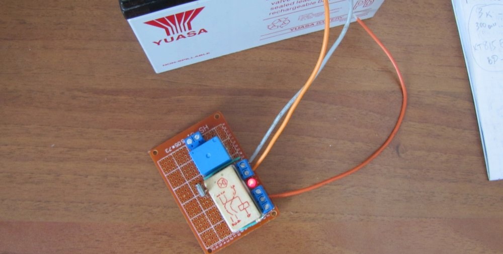
Everything is working fine. Watch a video about tests of this system.

Watch the test video

come back
Comment
  • bowtiesmilelaughingblushsmileyrelaxed relaxedsmirk
    heart_eyeskissing_heartkissing_closed_eyesflushedrelievedsatisfiedgrin
    winkstuck_out_tongue_winking_eyestuck_out_tongue_closed_eyesgrinningkissingstuck_out_tonguesleeping
    worriedfrowninganguishedopen_mouthgrimacingconfusedhushed
    expressionlessunamusedsweat_smilesweatdisappointed_relievedwearypassive
    disappointedconfoundedfearfulcold_sweatperseverecrysob
    joyastonishedscreamtired_faceangryragetriumph
    sleepyyummasksunglassesdizzy_faceimpsmiling_imp
    neutral_faceno_mouthinnocent
5+two=
Comments (10)
  1. Guest Sergey
    #1 Guest Sergey Guests January 30, 2018 09:16
    3
    Why such difficulties? 2 relays, a float from the drainage tank, a level sensor from the nine of any 12V power supply. And all these LEDs , transistors, resistors - into the furnace.
  2. Vladimir Gryadovkin
    #2 Vladimir Gryadovkin Guests 4 February 2018 12:27
    4
    The level sensor is from a washing machine and the solenoid valve is from it! It’s simple and ingenious!
  3. Guest Vladimir
    #3 Guest Vladimir Guests 2 September 2018 18:34
    1
    This system works great on a crusher hopper, only the end switches are different.
  4. Guest Roman
    #4 Guest Roman Guests October 5, 2018 11:12
    0
    The device is really useful. But your instructions are very UNinformative. Those who fumble around in microcircuits can assemble something like this without instructions, but for the ignorant it is not clear... how the sensors were powered, what their voltage is, etc. Show the diagram “live” in the photo with explanations of what-where-from-where-how much.
  5. Guest Nikolay
    #5 Guest Nikolay Guests 11 October 2018 19:15
    3
    The simplest circuit is assembled on one contact. Provides on/off switching and protection against dry running.
  6. Guest Alexey
    #6 Guest Alexey Guests 12 January 2019 23:38
    0
    Or you can assemble a circuit using the same principle, only one sensor...a throttle position sensor....so that you can change the level of actuation of the relay on and off at an adjustable height...analogous to the position of the air suspension above ground level, which can be raised and lowered ...and so that it pumps itself up in the required range???
  7. Guest Alexander
    #7 Guest Alexander Guests 18 April 2019 21:40
    1
    The second relay, if there is also an intermediate relay AKA "contactor", seems superfluous to me. I would add a “topping up” button, for example, after manually watering “half a barrel” and probably a control circuit from the “smart greenhouse” system. And so, there are no words.. The simplicity of the solution is only if you have talent.. Once, in one device, I made “triggers” out of relays, using the property of hysteresis (the difference in the operating and releasing currents), when the “start” button is shunted with a resistor, which does not allow the relay to “release” after releasing the button, it was turned off by the same “stop” button "for a break in the relay power supply...
  8. Guest Alex
    #8 Guest Alex Guests 21 May 2019 14:20
    2
    Thank you. that's what happened

    Later I will add floats and protection against dry running of the pump
  9. Novel
    #9 Novel Guests 10 April 2020 12:02
    4
    Hello. I am new to radio electronics and still have a poor understanding. I don’t understand the diagram, can you please tell me in more detail what goes where in which relay?
  10. Alex13
    #10 Alex13 Guests December 9, 2021 09:00
    2
    The diagram is drawn incorrectly.
    The reed switches of the upper level (GK2) and the emergency level (GK3) should be located not in parallel but in series. Otherwise it loses all meaning.

How to remove creaking laminate flooring without dismantling it

Do it yourself - crafts and master classes | Page 18

Making a tandoor from a barrel with an insulated bottom without mortar

How to make a simple coffee table with your own hands

«Do it yourself - with your own hands» - a site of interesting homemade products made from scrap materials and items at home. Step-by-step master classes with photos and descriptions, technologies, life hacks - everything a real master or just a craftsman needs for needlework. Crafts of any complexity, a large selection of directions and ideas for creativity.

We recommend reading

Washing machine error codes