Blocking – generator is a generator of short-term pulses repeated at fairly large intervals.
One of the advantages of blocking generators is their comparative simplicity, the ability to connect a load through a transformer, high efficiency, and connection of a sufficiently powerful load.
Blocking oscillators are very often used in amateur radio circuits. But we will run from this generator Light-emitting diode.
Very often when hiking, fishing or hunting you need a flashlight. But you don’t always have a battery or 3V batteries at hand. This scheme can start Light-emitting diode at full power from a nearly dead battery.
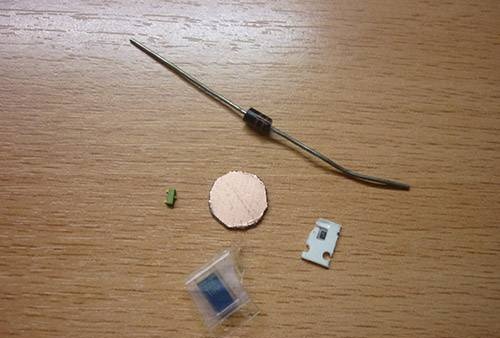
A little about the scheme. Details: any transistor (n-p-n or p-n-p) can be used in my KT315G circuit.
The resistor needs to be selected, but more on that later.
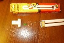
The ferrite ring is not very large.
And a high-frequency diode with a low voltage drop.
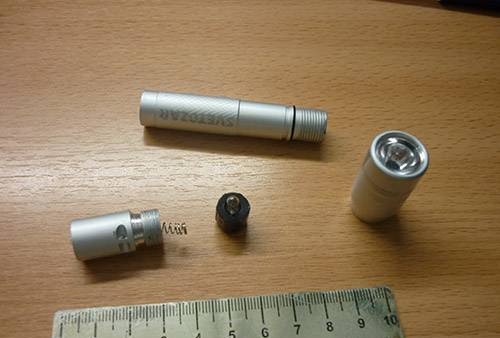
So, I was cleaning out a drawer in my desk and found an old flashlight with an incandescent bulb, burnt out, of course, and recently I saw a diagram of this generator.
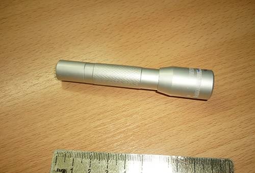
And I decided to solder the circuit and put it in a flashlight.
Well, let's get started:
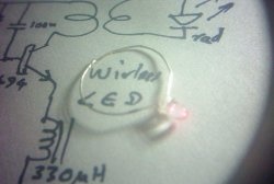
First, let's assemble according to this scheme.
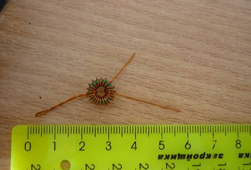
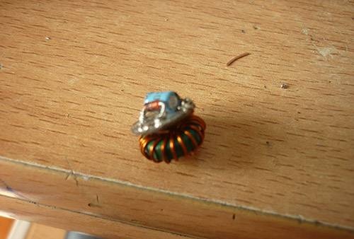
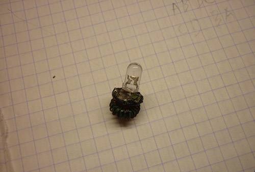
We take a ferrite ring (I pulled it out from the ballast of a fluorescent lamp) and wind 10 turns of 0.5-0.3 mm wire (it could be thinner, but it won’t be convenient). We wound it, make a loop, or a branch, and wind it another 10 turns.
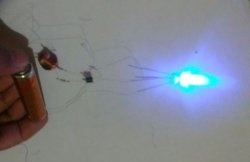
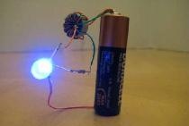
Now we take the KT315 transistor, Light-emitting diode and our transformer. We assemble according to the diagram (see above). I also placed a capacitor in parallel with the diode, so it glowed brighter.
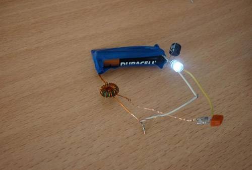
So they collected it. If Light-emitting diode does not light up, change the polarity of the battery. Still not lit, check if the connection is correct LED and a transistor. If everything is correct and still does not light up, then the transformer is not wound correctly. To be honest, my circuit didn’t work the first time either.
Now we complement the diagram with the remaining details.
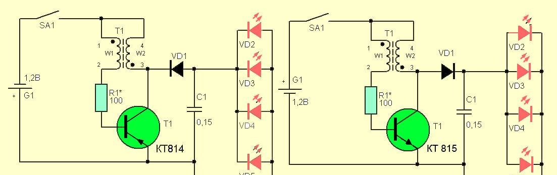
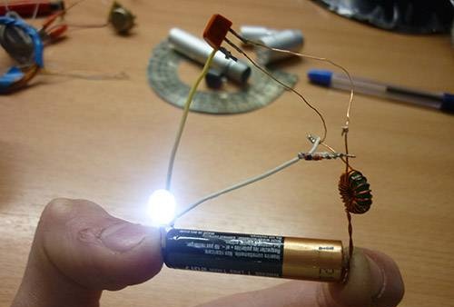
By installing diode VD1 and capacitor C1, the LED will glow brighter.

The last stage is the selection of the resistor. Instead of a constant resistor, we put a 1.5 kOhm variable one. And we start spinning. You need to find the place where the LED shines brighter, and you need to find the place where if you increase the resistance even a little, the LED goes out. In my case it is 471 Ohm.
Okay, now closer to the point))
We disassemble the flashlight
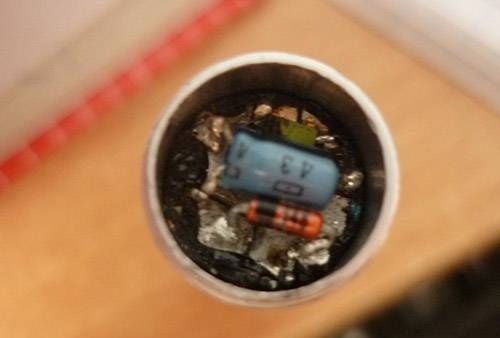
We cut a circle from one-sided thin fiberglass to the size of the flashlight tube.
Now we go and look for parts of the required denominations of several millimeters in size. Transistor KT315
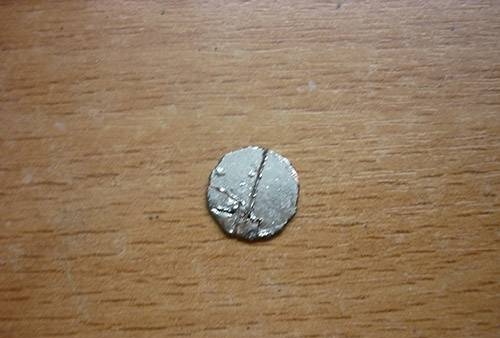
Now we mark the board and cut the foil with a stationery knife.
We tinker the board
We fix bugs, if any.
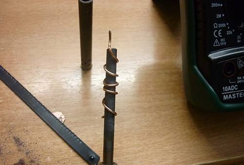
Now to solder the board we need a special tip, if not, it doesn’t matter. We take wire 1-1.5 mm thick. We clean it thoroughly.
Now we wind it on the existing soldering iron. The end of the wire can be sharpened and tinned.
Well, let's start soldering the parts.
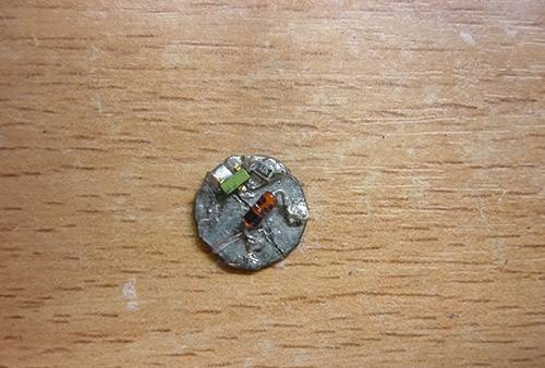
You can use a magnifying glass.
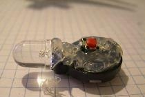
Well, everything seems to be soldered, except for the capacitor, LED and transformer.
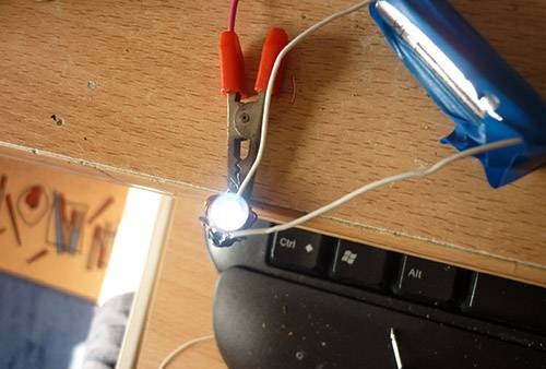
Now test run. We attach all these parts (without soldering) to the “snot”
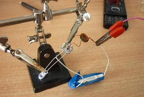
Hooray!! Happened. Now you can solder all the parts normally without fear
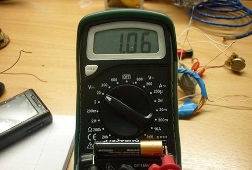
I suddenly became interested in what the output voltage was, so I measured
3.7V is normal for a high power LED.
The most important thing is to solder the LED))
We insert it into our flashlight; when I inserted it, I unsoldered the LED - it was in the way.
And so, we inserted it and made sure that everything would fit freely. Now we take out the board and cover the edges with varnish. So that there is no short circuit, because the body of the flashlight is a minus.
Now we solder the LED back and check again.
Checked, everything works!!!
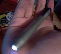
Now we carefully insert all this into the flashlight and turn it on.
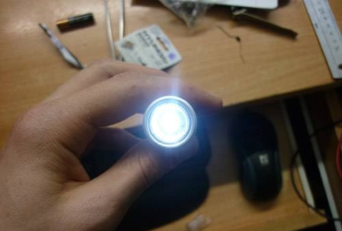
Such a flashlight can be started even from a dead battery, or if there are no batteries at all (for example, in the forest while hunting). There are many different ways to get a small voltage (insert 2 wires of different metals into a potato) and start an LED.

Good luck!!!