DIY do it yourself
Master classes, instructions, useful tips, recipes.
» » »Tesla coil on a single transistor or Brovin kacher
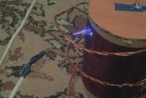
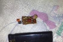
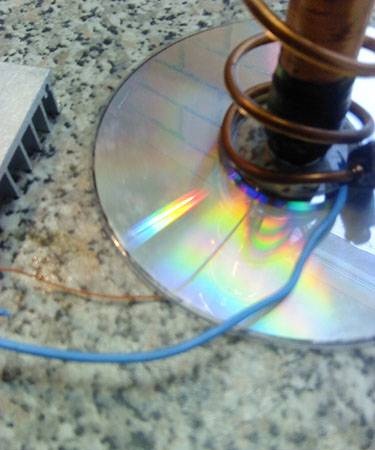
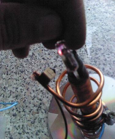
I present to you a very small Tesla coil on a single transistor or a Brovin kacher. In the Tesla coil, a very high alternating voltage of a high frequency is supplied to the primary winding, and as the primary winding feeds the collector current of the transistor, it was Brovin who found out that with such a generator circuit, a high voltage appears on the collector and discovered a new way to control the transistor and called this device Kacher, which means a oscillator reactivity. The kacher is a high-frequency high-voltage generator, as a result of which the so-called corona discharge can be seen at the terminal. Also around it there is a rather strong electromagnetic field capable of influencing radios mobile phones especially touch and other electronics. Therefore, in the photo of the working quality, stripes are noticeable in close-up. It was these devices that Tesla tried to transmit energy to a distance, whether he managed to do this is unknown. Now there was no other use as a toy. So, let's get started, we need to consider the scheme, it is very simple and solders in 10 minutes.


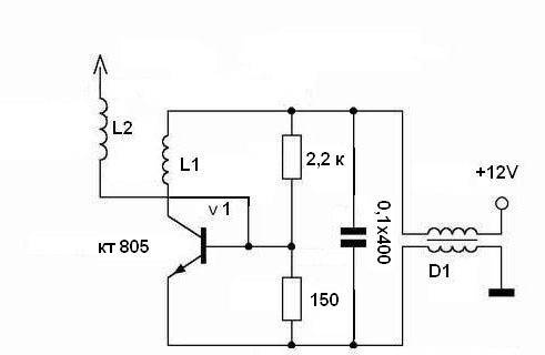
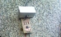
I redid it a little, instead of the inductor, a DC source of 12 V and electric. A capacitor with a capacity of at least 1000 microfarads, the more the better.
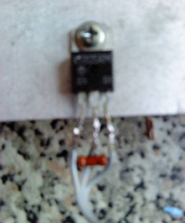
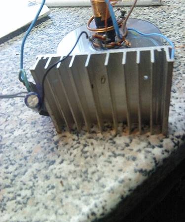
The transistor must be installed on a rather large radiator, otherwise it starts to warm up


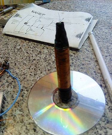
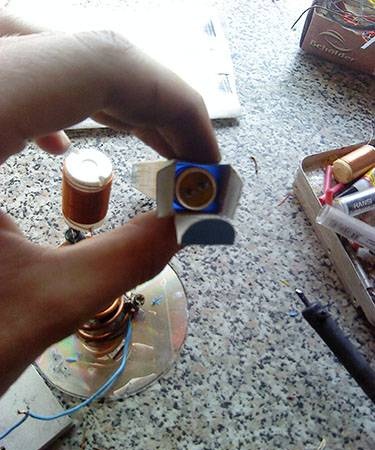
Then the most routine and tedious task is to be done, the L2 coil needs to be wound with a very thin wire of about 0.01 mm or a little thicker, but the finer it is, the greater the effect


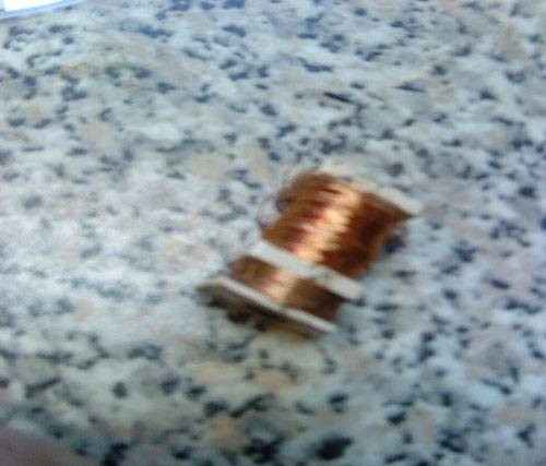
you need to wind it on a marker or something like that, but it must be a plastic cylinder, carefully turn it to a turn in one layer, if you wind around intermittently, coat with glue otherwise everything will go down the drain.
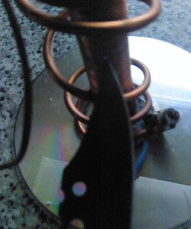
We stick a marker on a rack, a regular disk is great for this


then we twist the primary winding L1 of 2-5 turns with a very wire of very large cross-section, of the order of 2-4 mm, for convenience it is better to take a skeleton diameter, which should be almost two times the marker


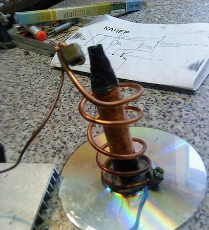
The lower tap from the marker, which goes to the base of the transistor, is better to put under the disk so that it does not touch the secondary winding.


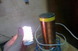
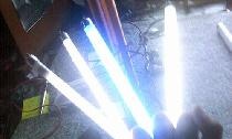
If everything is done correctly, then the circuit should work immediately, it is better to check with a fluorescent lamp, if there is no glow, swap the ends of the secondary winding (thick wire) or check if it touches the marker.


And so this is what can be done as a ready-made kacher
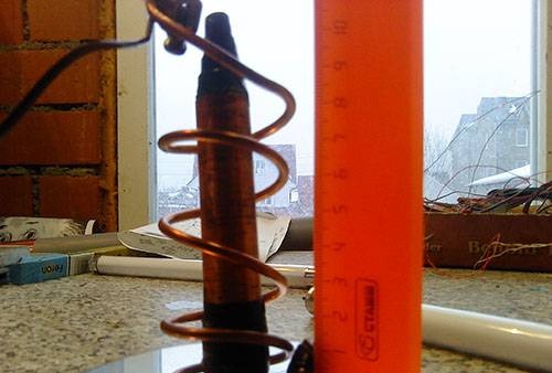
If you bring a discharge lamp to the quality, it starts to glow


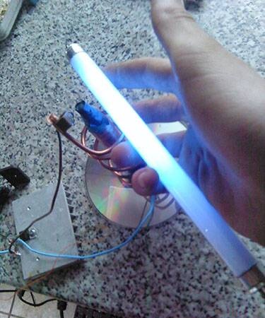
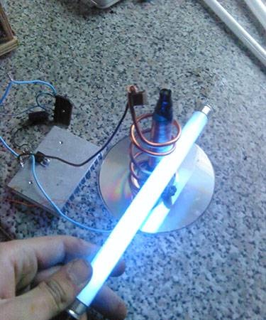
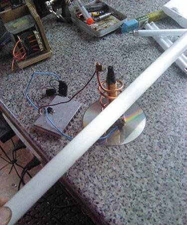
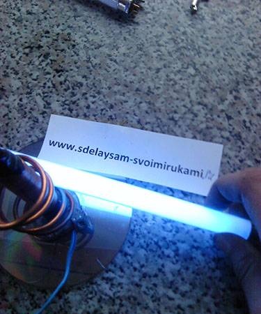
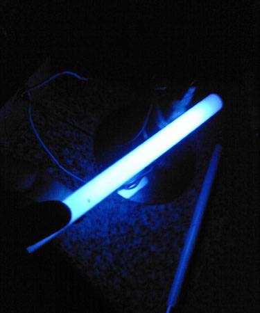
The same effect is observed with other similar lamps.


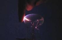
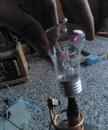
Also in a conventional incandescent lamp, you can see the so-called glow discharge that looks like a plasma ball looks very nice


You can simply touch something with metal, the discharge is almost invisible, due to the size of the quality
If you make a large model, you can make an ion engine, but here it will not work


The result is a simple and fairly cheap toy

The most expensive were
1.Transistor 30 r
2. Radiator 20 r

The rest was already in stock, but I think everything in total will not cost 150 rubles.

AND THE MOST BASIC INFLUENCE ON THE HUMAN ORGANISM, Despite the size, it’s rather small, so that it’s not worth getting carried away, otherwise a mild headache may appear, and it does not look very good. A STRONG ELECTROMAGNETIC FIELD INFLUENCES THE NERVOUS SYSTEM.ALSO DO NOT TOUCH THE DISCHARGES HANDS BECAUSE OF HIGH FREQUENCY OF THE PAIN THE ABSOLUTE WILL NOT BE THE MAXIMUM, A LITTLE BURN WILL REMAIN, BUT HARM IS AS MUCH AS FROM THE USUAL CURRENT, IF NOT MUCH.


P.S. Video with a big model:


Wishing to repeat good luck!

come back
Comments (61)
  1. [) eNiS
    #1 [) eNiS Guests April 18, 2011 13:05
    1
    not necessarily for the whole, I wound 5 turns with a spiral and did not stretch. then stretched, the result was the same as with unstretched
  2. NOTFRONT
    #2 NOTFRONT Guests April 4, 2011 18:35
    0
    I do not agree! If the throttle and capacitor are canceled by 0.1 (as the author did), then this will not be a kacher, but an ordinary three-point generator or a blocking generator.
  3. NOTFRONT
    #3 NOTFRONT Guests April 4, 2011 19:05
    0
    And the video says that the voltage is 2000 volts! this is not so, the voltage in the Tesla coil is about 100,000 volts! FACT !!!!
  4. [) eNiS
    #4 [) eNiS Guests April 4, 2011 19:06
    0
    I collected this, I just fed it from the fuel assembly. The discharge lamp glowed, but the arcs were only about 0.5 mm and not bright ((
  5. Andrew
    #5 Andrew Guests April 5, 2011 10:10
    0
    and where does the second wire from the second winding go?
  6. [) eNiS
    #6 [) eNiS Guests April 5, 2011 16:52
    0
    Nowhere, he leaves))) Arcs should go from him. In the 5th figure, it is visible but poorly. Such a hair sticks out of a coil
  7. Veent
    #7 Veent Guests April 17, 2011 22:23
    0
    I think 5..7 is enough the main thing is to evenly stretch the entire length of the coil
  8. Borigal
    #8 Borigal Guests February 6, 2012 5:31 p.m.
    0
    as an option, it is denser to wrap with a thin copper tube, having smeared the pre-coating part with contact gel and sealed everything with cold welding, except for the contacts of course,
    Put cold water into the tube or even connect it to the air conditioner in an even more advanced version, but this is a military installation)

    I’m interested in whether anyone with a kucher managed to get a thermal effect exceeding the power consumed from the network and is there any reason to develop such devices for heating systems in a private house?
  9. Denisov
    #9 Denisov Guests June 1, 2011 00:40
    1
    a few questions:
    1. What n / a transistor to take: KT805, KT819, KT872, and what types?
    2. Is a 10000mF capacitor suitable?
  10. Denisov
    #10 Denisov Guests June 1, 2011 00:46
    0
    I saw a sugha to a wire a needle attached a foil ball to the needle and in the middle of the needle 2 wires in different directions.
    so, these wires were spinning, like an ion engine smile
  11. Denisov
    #11 Denisov Guests June 1, 2011 00:47
    1
    a lot of smile
    1000-1500 if so thin
  12. raar
    #12 raar Guests June 1, 2011 17:57
    0
    please tell me the 0.1x400 capacitor is 100 nanofarads?
  13. feelloff
    #13 feelloff Guests June 1, 2011 18:12
    1
    1 nF = 1000 pF, or 0.001 μF
  14. raar
    #14 raar Guests June 2, 2011 20:36
    0
    Thank you, I just wanted to know if it’s a frequency setting of 100 nanofarads? or at 1000uf
  15. raar
    #15 raar Guests June 2, 2011 20:37
    0
    otherwise the article mentioned only a capacitor of 1000 microfarads and more
  16. Veent
    #16 Veent Guests June 2, 2011 22:53
    0
    in the diagram, a capacitor of 0.1 uF 400 V, for the sake of experiment, you can put a diode bridge (rectifier) ​​and an electrolyte. 1000 uF capacitor and higher
  17. raar
    #17 raar Guests June 3, 2011 10:28
    1
    it turns out we cancel the inductor and instead of the capacitor 0.1x400 set 1000 microfarads and above?
  18. Veent
    #18 Veent Guests June 3, 2011 10:25 p.m.
    0
    we don’t cancel the throttle; we simply straighten the alternating current coming from it to direct; in this case, it goes along the upper bus + along the lower - and we add the capacitor
  19. raar
    #19 raar Guests June 4, 2011 09:42
    0
    all understand thanks
  20. [) eNiS
    #20 [) eNiS Guests June 6, 2011 09:41
    0
    I even can not understand why this ... kacher does not rob me. First he collected everything on the KT838, then he found the KT805BM. In no case did it work (((I even assembled with a inductor (I pulled out 2.9 Ohm resistance of each winding from the Vidic board). Power was supplied 9V from the crown, 13.5V from the transformer through the rectifier and finally 36V, at the output the secondary all the time was 0V (Where, in what and why do I have a mistake?
  21. feelloff
    #21 feelloff Guests June 6, 2011 19:18
    1
    Try resistors to "play". Look at what offset is applied to the transistor.And do not forget to try to swap the windings of one of the coils.
  22. [) eNiS
    #22 [) eNiS Guests June 6, 2011 20:36
    0
    But how to understand the bias? I'm in electronics in terms of not very strong))
  23. feelloff
    #23 feelloff Guests June 6, 2011 20:41
    0
    Well, look at the current consumed, it should be about 10..100 mA without generation. Pick up something like this top resistor.
  24. Denisov
    #24 Denisov Guests June 8, 2011 16:16
    0
    I do not plow !!!
    powered by a BP computer (12 volts)
    The transistor took KT805 (different: large in metal, flat in plastic)
    The transistor did not even get warm! angry
    Resistance L2 3.2 Ohm

    resistors took variables, tuning it before that!
  25. Veent
    #25 Veent Guests June 8, 2011 19:14
    0
    You can also try this little difference scheme, but maybe some will be easier [center][/ center]
  26. [) eNiS
    #26 [) eNiS Guests June 8, 2011 19:26
    0
    And my transistor almost melted, and the resistors were boiling. And the scheme also did not work ((
  27. Denisov
    #27 Denisov Guests June 8, 2011 21:45
    0
    It worked a little, but the gas in the lamp did not catch fire!
    the transistor with a radiator warmed up like an iron and smoked
    There were no resistors !!!
  28. Veent
    #28 Veent Guests June 8, 2011 21:59
    0
    Yes, that's right, as for the transistor, just in case, if the kt805 is put upwards, the emitter, the collector base, and the collector are directly connected to the metal part of the transistor on the left side of the wire, and check if it is broken, if it’s working, attach + to the collector - the tester and measure the resistance it should be about 400-500 ohms maybe more
  29. [) eNiS
    #29 [) eNiS Guests June 9, 2011 15:22
    0
    With those transistors that I did not work, they were punched. I found a new whole kt838 connected, the transistor hardly warms up but doesn’t work anyway ((I put it together cleverly: multivibrator + fuel assemblies. Decent arcs and the Tesla coil can be started, I think, to start ... And not much is not heated
  30. Denisov
    #30 Denisov Guests June 9, 2011 15:47
    0
    Well, I know that!
    only with nefig resistors I do not understand !!!
    2.2K and 150 is, as I understand it, only marking, and what should be the resistance of each?
    I shashol a whole bunch of 2.2k transistors, and each has a different resistance!
  31. NOTFRONT
    #31 NOTFRONT Guests June 12, 2011 19:26
    0
    This is not Tesla work, but a high voltage generator
  32. [) eNiS
    #32 [) eNiS Guests June 12, 2011 21:21
    0
    Everything was assembled by this Tesla coil. Everything works. You can do almost everything that doesn’t light up on the video only at a great distance from the coil. I wrapped a small coil. And yet the ion engine fails
  33. Veent
    #33 Veent Guests June 16, 2011 09:50
    0
    the ion engine if I’m not mistaken works at a voltage of more than 25 kV
  34. [) eNiS
    #34 [) eNiS Guests June 17, 2011 09:04
    1
    it’s unlikely that I had such a voltage on it 5-10 kV cutoffs ((maybe a little more. I go from the fact that 1mm of punched air is 1000V
  35. CAH9I
    #35 CAH9I Guests November 7, 2011 20:01
    0
    I did, according to the second scheme, but others took resistance, the upper 10kΩ lower 47kΩ and the conder at 10000mkF, it worked but more powerful, since the secondary was larger (1250 turns on a PVC pipe 50mm diam) the source took from the scanner 15v 0.8am)
  36. Andrey1
    #36 Andrey1 Guests December 23, 2011 22:44
    1
    I assembled this device, the primary device on the 50mm pipe with 0.1 mm 2000 wire, the secondary 4 turns on the 80mm pipe with a thick wire ... the kacher did not start the first time ... but removing the 150 ohm resistor from the circuit in general, it worked .... after what the trimmer added by 30kΩ in series with 2.2kΩ and achieved the optimal operation of the device ... put this whole thing together on the ct805AM, powered it from a 12V battery ... I continue to experiment :-)
  37. Cat hunter
    #37 Cat hunter Guests January 9, 2012 10:06
    0
    C1 how many volts?
  38. Igor3856
    #38 Igor3856 Guests January 18, 2012 02:47
    1
    All! Hurrah! Collected! so: here is the diagram (personally verified) [center][/ center]
  39. Igor3856
    #39 Igor3856 Guests January 18, 2012 02:55
    0
    Litter for quality :(
    [b] Cat-Hunter [/ b] 1) With the wire you have everything ok, with the capacitor ok, with the transistor ok and the trip with the resistors is not ok you need to take in pairs somewhere 10 kOhm and 47 kOhm
    2) Check all the connections, especially the transistor leads, whether the base and collector are correctly connected at the base of the transistor and the collector is reversed (I personally did) change the resistors or put at least a little more like 20 kOhm and 5 kOhm, and check the leads with the transistor, then everything will start! And even when you will run, if it does not start, change the conclusions of the primary!
  40. Cat hunter
    #40 Cat hunter Guests January 27, 2012 17:24
    0
    EVERYTHING IS WORKING !!! URAAAAAA !!!
    It turned out that the current for my KACHER is weak!
    CONNECTED 8 CROWN (9 AND VOLT BATTERIES) = 72 VOLTS, AND EVERYTHING IS OK!
    The transistor is ONLY HEATED
    WHAT CAN BE DONE TO ELIMINATE THIS PROBLEM?
  41. Sasha
    #41 Sasha Guests August 8, 2012 12:06
    0
    And will it work from 8.6V DC with a 10v 2200uF capacitor with a resistor and 2.2kom 140ohm the transistor is the same kt805am primary with a diameter of 4.1 5 turns and a secondary with a diameter of 0.5mm (xs skoka skoka nada wound) and what will be the voltage \ yes and more at what power should resistors be
  42. Zhenya
    #42 Zhenya Guests September 12, 2012 18:24
    0
    will work from the kt818b transistor?
  43. hack-tt
    #43 hack-tt Guests October 26, 2012 12:33
    1
    Hello everyone ... I am collecting one of the proposed schemes. Explain those to me !!!! capacitor per 1000 microfarads how many volts ????? I got confused in the resistors ((((are they the correct value for the resistance as shown in the diagram ??? in my head everything was mixed ...
    [center] [img] http://washerhouse.com/3/en/pictures_users/1/6.jpg [/ img] [/ center]
  44. antoxan
    #44 antoxan Guests November 26, 2012 22:30
    0
    Tell me please, I did everything as it should, but put the KT805A transistor instead of the kt805 and it doesn’t plow for me, tell me why ???
  45. Docker_martin
    #45 Docker_martin Guests December 20, 2012 17:48
    0
    Hello everyone ... Do you think the details from BP Comp are suitable for Tesla Coil?
  46. yuri
    #46 yuri Guests April 17, 2013 23:10
    0
    Did you try to measure the field frequency?
  47. Veent
    #47 Veent Guests April 23, 2013 22:18
    0
    Quote: yuri
    Did you try to measure the field frequency?

    The oscilloscope was not at hand.
  48. jjj
    #48 jjj Guests May 7, 2013 17:25
    0
    Quote: Andrew
    and where does the second wire from the second winding go?

    just sticks up
  49. Daniel
    #49 Daniel Guests July 17, 2013 07:20
    0
    Without changing the scheme of the author, he wound the coil on a cylinder from a glue gun, 1200 turns, 0.1 mm wire. Hedgehog glows at 3cm () corona discharge, the lamps light up from 40cm!
  50. Sergey
    #50 Sergey Guests September 23, 2013 10:18
    3
    Here is a working diagram of the quality of http://cs305402.vk.me/v305402318/4888/k86hMo483fU.jpg

Read also

Error codes for washing machines