DIY do it yourself
Master classes, instructions, useful tips, recipes.
» » »LED cube 3x3x3 not programmable


I think many wanted to collect such a cube, but not everyone had the opportunity to purchase a microcontroller (MK), and not everyone knows how to program. So here is an alternative:


No programming required, the circuit is simple and all details are accessible. And the CD4020 chip provides a variety of compositions that are not inferior to programmable cubes.


It's time to move from words to deeds)))

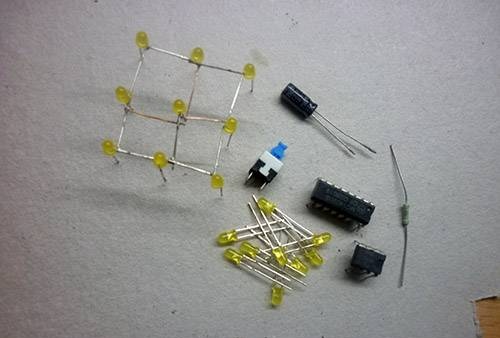
List of used parts with a description:

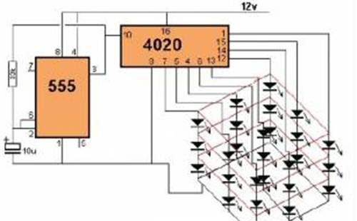
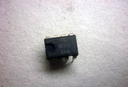
1) KR1006VI1 (NE555)

The chip includes about 20 transistors, 15 resistors, 2 diodes. The output current is 200 mA, the consumption current is approximately 3 mA more. Supply voltage from 4.5 to 18 volts. The accuracy of the timer does not depend on changes in the supply voltage and is no more than 1% of the calculated value.


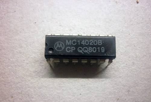
2) K561IE16 (CD4020, MC14020)

14-bit binary counter divider.


3) LEDs to your taste 27pcs
4) 33K resistor
5) Capacitor 10µ
6) Latch micro switch (optional)
7) Krona 9V
8) Chip panels (optional)
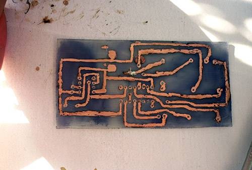
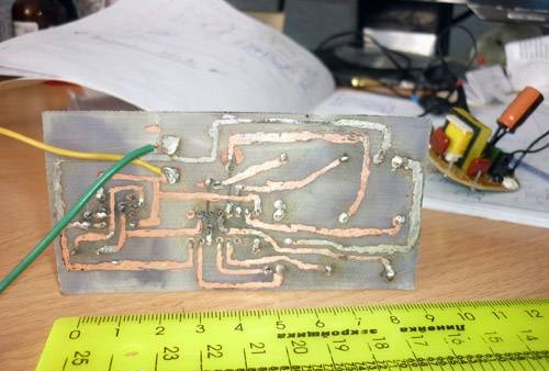
So, we draw a printed circuit board on fiberglass and lay etched.


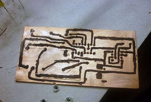
In the meantime, our board will be etched. Let's deal with the most difficult part - the cube itself.
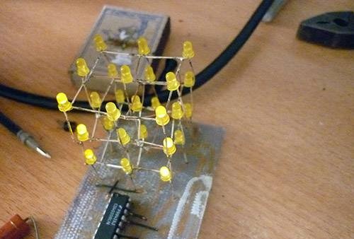
We drill holes in plywood (cardboard) under the LEDs and insert them there. Now we bend all the cathodes (minuses) clockwise (or counterclockwise, as you prefer) and solder them. Solder the wires yourself on the middle LED.


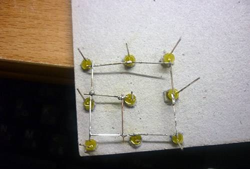
Also do the rest of the floors


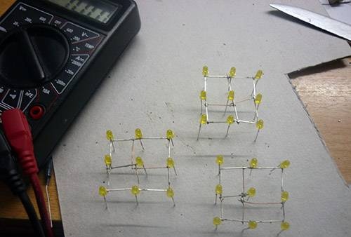
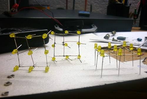
Now we need to solder them together. Only now we solder anodes (pluses)


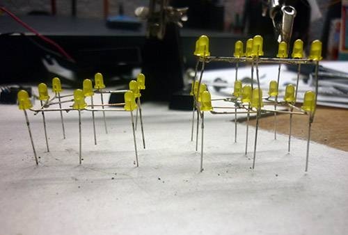
Now also solder the third floor


Done !!)))


Now we take our etched board and drill holes


First we solder the jumpers, and then the details.


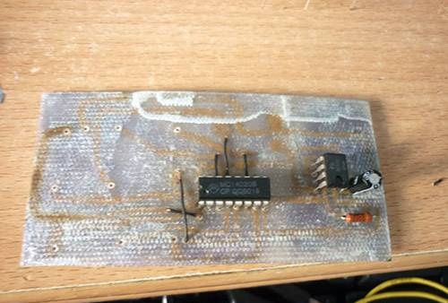
Now the final touch - solder the cube.


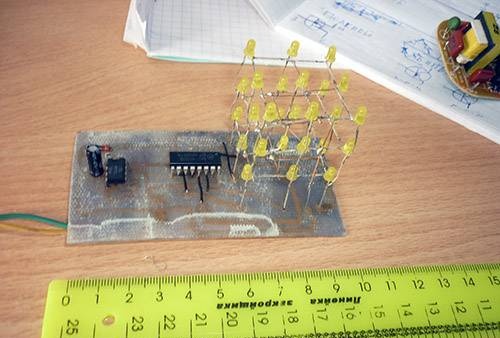
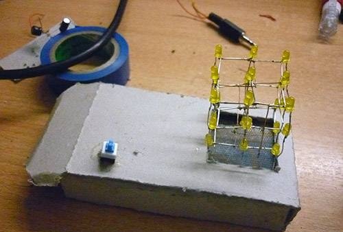
Now we connect 12V as it is written on the circuit. URA works:


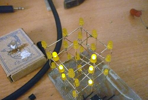
After a couple of minutes, everything went out ((.

Correctly, the CD4020 chip is not designed for such a voltage and it just burned out for a simple one. And you have to change the chip - to solder and solder a new one. For this, we needed panels for microchips. I did not put them on anything and paid ((

In the future, to avoid this, I put the crown 9B. This has its advantages, the cube can be carried with you, it does not need a socket and the microcircuit will no longer burn. But there are also disadvantages - periodically you have to change the battery.


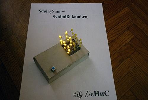
For my cube I made a box of cardboard. Here's what I got:


come back
Comments (22)
  1. Veent
    #1 Veent Guests April 3, 2011 16:38
    0
    it turned out very well, if only the LEDs were brighter, it could finally be cool.
    Yes, and you can’t tell the music ator? smile
  2. NOTFRONT
    #2 NOTFRONT Guests April 3, 2011 17:02
    0
    Send me a photo! music - Hey There Delilah (Plain White T's)
  3. Veent
    #3 Veent Guests April 3, 2011 17:26
    0
    I didn’t do this photo as most commentators I advise only)) I just saw the same cube with 5000 superbright LEDs
  4. NOTFRONT
    #4 NOTFRONT Guests April 3, 2011 17:40
    0
    Ah, got it. cool
  5. [) eNiS
    #5 [) eNiS Guests April 4, 2011 19:00
    1
    I am very glad that I liked the topic))
  6. Denisov
    #6 Denisov Guests June 6, 2011 18:19
    0
    I drew a marker on the board ???
  7. [) eNiS
    #7 [) eNiS Guests June 9, 2011 15:16
    0
    In the sense of? You mean that the board itself is blackish? This is for some reason left after the solvent) And if the roads are not even, my printer is buggy so I have to paint them with varnish on top (
  8. Lloha2012
    #8 Lloha2012 Guests August 9, 2011 21:08
    0
    and more precisely it is possible ??? !!! surprisedcool
  9. larok
    #9 larok Guests October 13, 2011 10:06 p.m.
    0
    the question is where on the diagram + and where -?
  10. NOTFRONT
    #10 NOTFRONT Guests October 14, 2011 08:43
    0
    + goes to 12V, and minus under the letters washerhouse.com/3/en
  11. Psihin
    #11 Psihin Guests October 24, 2011 8:20 PM
    0
    Guys, is it possible to make a heart by this principle? if yes, then advise, please ...
  12. vov @ n
    #12 vov @ n Guests December 7, 2011 23:10
    1
    crycrycrycrycrycrycrycrycrycrycry
    something doesn’t burn .....
  13. zone
    #13 zone Guests December 8, 2011 21:38
    0
    Or you can make a 5x5x5 cube without microcontrollers. If possible, please post to the site.
  14. Toha
    #14 Toha Guests December 19, 2011 17:45
    0
    I’ll immediately say without mikruhi there will be many transistors that way 50 pieces .....
  15. Van der
    #15 Van der Guests January 25, 2013 09:25
    1
    Dear author, do not mislead people. By soldering the LEDs in this way, you will get a PARALLEL connection, not a SERIAL connection, as in the diagram. Both microcircuits are designed for a supply voltage of up to 15 volts. 4020 burned out due to the fact that all this works through one place and a large current flows through the 4020 outputs. It is more correct to solder this cube from vertical columns by 3 LEDs connected in series.
  16. Van der
    #16 Van der Guests January 25, 2013 09:32
    0
    It all works for me from 12 Volts, I attached a 100 Ohm current limiting resistor to each LED column. If stable operation does not work, connect the 2nd and 11th outputs at the 4020.
  17. Van der
    #17 Van der Guests January 25, 2013 09:37
    0
    The schema is better [center] [img] http://washerhouse.com/3/en/pictures_users/1/16.jpg [/ img] [/ center]
  18. Boris
    #18 Boris Guests September 17, 2013 9:22 p.m.
    0
    Today I made such a cube, it works, but the problem is that all the LEDs are constantly on and do not go out. what could be the reason please tell me.
  19. Atay
    #19 Atay Guests May 26, 2015 10:03
    0
    not how I can not find "-" tell me
  20. Andrei
    #20 Andrei Guests November 9, 2015 14:38
    0
    [b] Atay [/ b], connect 1 to pin 555 of the microcircuit.
  21. Dima
    #21 Dima Guests February 29, 2016 21:18
    0
    7 and 5 contacts where do they go?
  22. Zhenek
    #22 Zhenek Guests March 7, 2017, 21:01
    0
    Such a cube will not work in life! The diodes must be soldered sequentially, in columns and it is MANDATORY to put a current-limiting resistor on each column.

Read also

Error codes for washing machines