Do it yourself
Life hacks, master classes, useful tips, recipes.
home » Electronics » Simple circuits » Simple color music using LEDs

A very simple three-channel RGB color music on LEDs does not contain scarce or expensive components. All elements can be found in anyone, even the youngest radio amateur.

The operating principle of color music is classic and has truly become the most popular. It is based on dividing the sound range into three sections: high frequencies, mid frequencies and low frequencies. Since color music is three-channel, each channel monitors its frequency limit and when its level reaches the threshold value, it lights up Light-emitting diode. As a result, when playing music, a beautiful lighting effect is created, when blinking LEDs various colors.

Simple color music scheme

Three transistors - three channels. Each transistor will act as a threshold comparator and when the level exceeds 0.6 Volts, the transistor opens. The load of the transistor is Light-emitting diode. Each channel has its own color.

In front of each transistor there is an RC circuit that plays the role of a filter. Visually, the circuit consists of three independent parts: the upper part is the high-frequency channel. The middle part is the mid frequency channel.Well, the lowest channel in the diagram is the low-frequency channel.

The circuit is powered by 9 Volts. The input receives a signal from headphones or speakers. If the sensitivity is not enough, then you will need to assemble an amplifier stage on one transistor. And if the sensitivity is high, then you can put a variable resistor at the input and use it to regulate the input level.

You can take any transistors, not necessarily KT805, here you can even install low-power ones like TK315, if there is only one load Light-emitting diode. In general, it is better to use a composite transistor like KT829.

LEDs super bright, got it here - AliExpress.

You can also take all the other components of the circuit there.

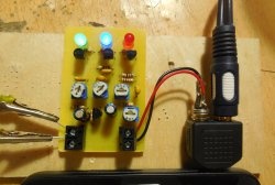
Assembly of color music

You can assemble the color music using wall-mounted mounting or on a circuit board, as I did.

No setup is needed, it’s assembled, and if all the parts are suitable, everything works and blinks without problems.

Is it possible to connect an RGB LED strip to the input?

Of course you can, to do this we connect the entire circuit not to 9 V, but to 12. In this case, we throw out the 150 Ohm quenching resistor from the circuit. We connect the common wire of the tape to plus 12 V, and distribute the RGB channels among the transistors. And, if the length of your LED strip exceeds one meter, then you will need to install transistors on radiators so that they do not fail due to overheating.
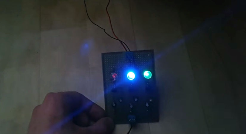
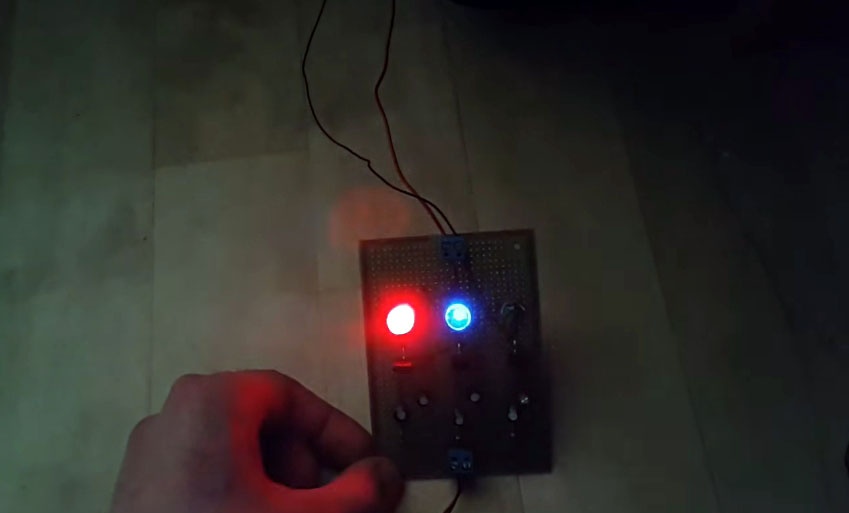
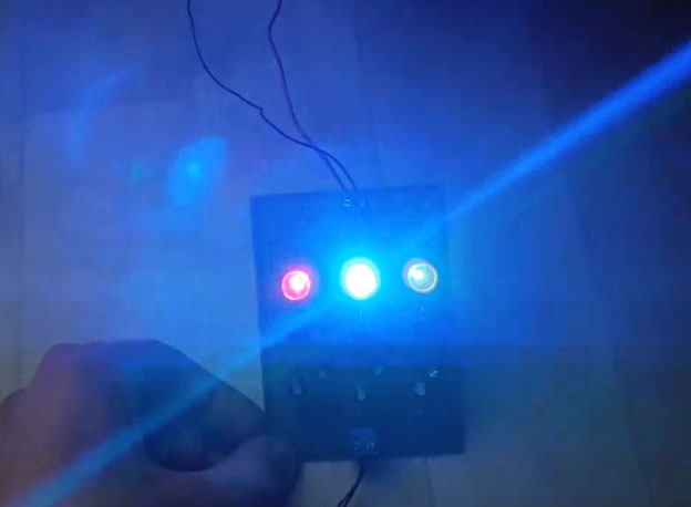
Color music at work

Looks quite beautiful. Unfortunately, this cannot be conveyed through pictures, so watch the video.

Simple color music using LEDs

Watch the video of operation and assembly

come back
Comment
  • bowtiesmilelaughingblushsmileyrelaxed relaxedsmirk
    heart_eyeskissing_heartkissing_closed_eyesflushedrelievedsatisfiedgrin
    winkstuck_out_tongue_winking_eyestuck_out_tongue_closed_eyesgrinningkissingstuck_out_tonguesleeping
    worriedfrowninganguishedopen_mouthgrimacingconfusedhushed
    expressionlessunamusedsweat_smilesweatdisappointed_relievedwearypassive
    disappointedconfoundedfearfulcold_sweatperseverecrysob
    joyastonishedscreamtired_faceangryragetriumph
    sleepyyummasksunglassesdizzy_faceimpsmiling_imp
    neutral_faceno_mouthinnocent
5+two=
Comments (13)
  1. Alexey Kovalev
    #1 Alexey Kovalev Guests 18 December 2017 18:15
    8
    It's funny to see electronic crafts of our youth in the 60s on modern radio components. I'm glad that today someone is interested in these simple universal devices.
    1. Dmitriy
      #2 Dmitriy Guests January 7, 2018 10:47
      3
      The circuit is standard, only we made it using thyristors KU-201, or better yet KU-202, and incandescent lamps or garlands.
  2. Anatoly
    #3 Anatoly Guests December 21, 2017 15:00
    5
    There are 6 capacitors on the assembly, and on the diagram there are 5. Which ones should be.
    1. Vlentin
      #4 Vlentin Guests 21 December 2017 15:18
      3
      See the diagram. Don't look at the video, there is no need for one capacitor in the high-frequency filter.
  3. Sergey
    #5 Sergey Guests December 23, 2017 20:40
    8
    The circuit is unsuccessful - why did you save resistors at the output? When everyone is turned on, the current of each will be three times less than the standard...
  4. Guest Nikolay
    #6 Guest Nikolay Guests 10 February 2018 11:20
    2
    The circuit can be connected not through a PC power supply, but through a step-down transformer from 220 V to 12 V?
  5. Michael
    #7 Michael Guests 9 July 2018 19:13
    4
    The circuit works, but my light is blue Light-emitting diode even without giving a signal. What can be done about this and what could be the reason?
  6. Paul
    #8 Paul Guests 12 July 2018 10:34
    0
    I liked it, I'll try to collect it
  7. Anton
    #9 Anton Guests July 31, 2019 11:14
    0
    What kind of capacitors? Voltage is not written. I'm just learning, I don't really understand it yet...)
  8. Alexander Lindeman
    #10 Alexander Lindeman Guests 29 February 2020 16:14
    3
    Primitively located LEDs: direct light from them into the eyes is only annoying. If the speaker diffuser is white, you need to install all three LED into the speaker (at the edge of the speaker), in one row next to each other, separated from each other by a light-proof partition. Direct the diode beams in parallel directly to the surface of the speaker. Options can be experimented with. As a result, you will get a whole palette of colors on the white background of the diffuser, and not a three-color flasher right in your eyes. The result is a color-musical kaleidoscope. In the old days, I did this by directing the rays of a powerful color setting directly at the white wall of the room. The whole room shimmered with all the colors of the rainbow and its shades!
  9. Radionub
    #11 Radionub Guests 11 July 2020 14:18
    1
    Good afternoon. Please tell me how to connect the parts together. Otherwise, I put them on the circuit, but I don’t know how to solder them. Please help. I can’t figure it out myself. Thank you in advance for your help.
  10. Sergey Koshkin
    #12 Sergey Koshkin Guests 26 October 2021 15:48
    3
    This digital control unit will not work without a preamplifier. Besides, we saved on resistors, why is there only 1 resistor on the plus side? It will get very hot. The transistors are chosen terribly; it is better to use low-frequency switching ones. To adjust the sensitivity, a variable resistor would be installed. Because of the preamplifier, the circuit is not working.

How to insulate a house with mineral wool

Ribbon and bead bracelet | Do it yourself

How to build a children's playhouse

How to restore a burnt-out muffler without welding with your own hands

«Do it yourself - with your own hands» - a site of interesting homemade products made from scrap materials and items at home. Step-by-step master classes with photos and descriptions, technologies, life hacks - everything a real master or just a craftsman needs for needlework. Crafts of any complexity, a large selection of directions and ideas for creativity.

We recommend reading

Washing machine error codes