Tester circuit
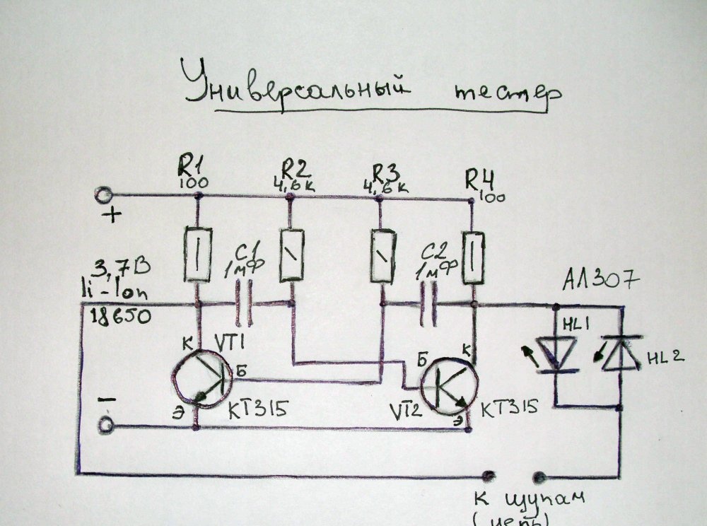
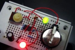
The tester contains the minimum number of elements that are sure to be found in the household, even for beginner radio amateurs. The whole circuit is essentially one multivibrator assembled on transistors. It generates rectangular pulses. The controlled circuit is connected to the shoulders of the multivibrator in series with two LEDs, counterclockwise. As a result, the circuit under test is tested with alternating current.
The principle of operation of the tester to check the radio components
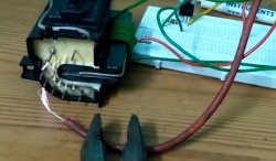
An alternating current, approximately equal in amplitude to the power source, is removed from the working multivibrator. Initially, the LEDs do not light because the circuit is open. But if you close the probes, then the alternating current will run through the LEDs. At this time, alternating current with a frequency of approximately 300 Hz will run through the LEDs. As a result of counter-parallel switching on, the LEDs will flash alternately, but due to the high generation frequency this will not be visible to the human eye, but it will be seen that both LEDs are just lit at the same time.
What does it give? - You ask. For example, if you connect a diode to the probes, then only one LED will light up, since the alternating current will run only after one period. As a result, it will immediately be clear that the connected diode is working. The same thing is observed when checking the transistor transitions.
The main convenience of this tester is that the diode transition immediately works or not. No need to turn the elements under the polarity of the tester, as in a conventional multimeter. This gives a huge advantage when checking a large number of radio elements, and indeed it is very convenient.
Other elements or circuits can also be checked for breakdown or breakage.

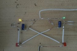
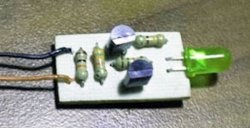
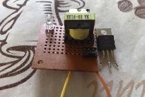
You can assemble the tester on the board or by mounting it. It is better to take LEDs of different colors, so that you can see clearly visually visible work.

Also, using this simple device, you can in two ways determine where the cathode and anode of an unknown diode are. But for this, it is necessary to mark the location on the LEDs of the tester.
As a power supply, I used a lithium-ion battery with a voltage of 3.7 V. But you can take 2-3 "little" 1.5 V batteries connected in series.
In general, the thing is very necessary. I recommend that you repeat this non-tricky device. And you are provided with convenience in work, since in most cases it is required to determine the serviceability of a radio element, and not its parameters.