One of the simplest circuits in amateur radio electronics is an LED flasher on a single transistor. Its production can be done by any beginner who has a minimum soldering kit and half an hour of time.
Although the circuit under consideration is simple, it allows you to clearly see the avalanche breakdown of the transistor, as well as the operation of the electrolytic capacitor. Including, by selecting the capacity, you can easily change the blinking frequency LED. You can also experiment with the input voltage (in small ranges), which also affects the operation of the product.
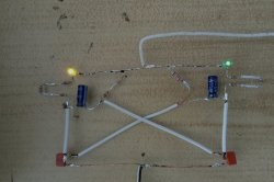
Design and principle of operation
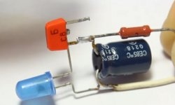
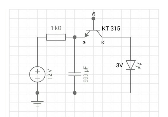
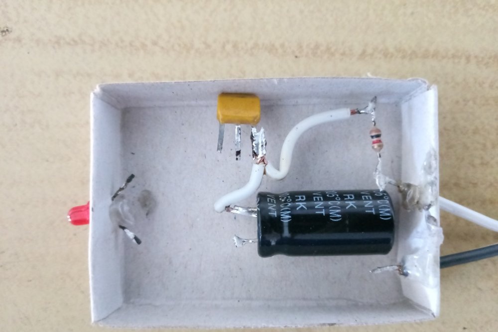
The flasher consists of the following elements:
- power supply;
- resistance;
- capacitor;
- transistor;
- Light-emitting diode.
The scheme works on a very simple principle. In the first phase of the cycle, the transistor is “closed”, that is, it does not pass current from the power source. Respectively, Light-emitting diode does not light up.
The capacitor is located in the circuit before the closed transistor, therefore it accumulates electrical energy.This happens until the voltage at its terminals reaches a value sufficient to ensure the so-called avalanche breakdown.
In the second phase of the cycle, the energy accumulated in the capacitor “breaks through” the transistor, and the current passes through Light-emitting diode. It flashes for a short time and then goes out again as the transistor turns off again.
Then the flasher operates in cyclic mode and all processes are repeated.
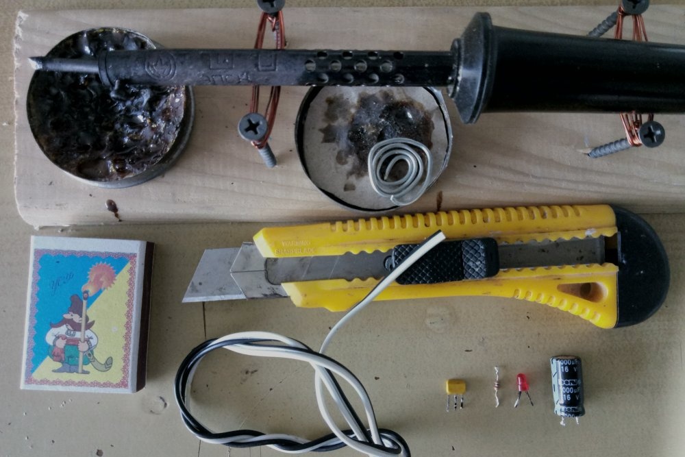
Necessary materials and radio components
To assemble an LED flasher with your own hands, powered by a 12 V power source, you will need the following:
- soldering iron;
- rosin;
- solder;
- 1 kOhm resistor;
- capacitor with a capacity of 470-1000 μF at 16 V;
- transistor KT315 or its more modern analogue;
- classical Light-emitting diode;
- simple wire;
- 12V power supply;
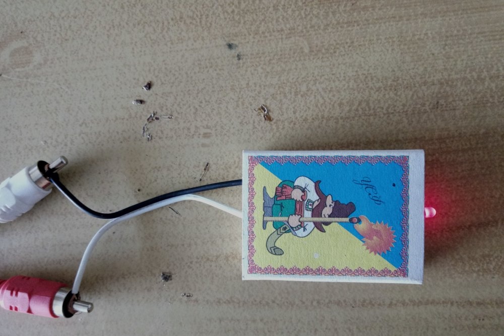
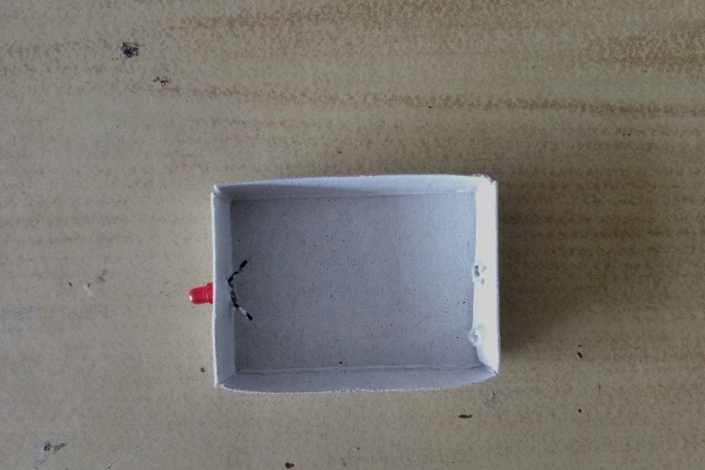
- matchbox (optional).
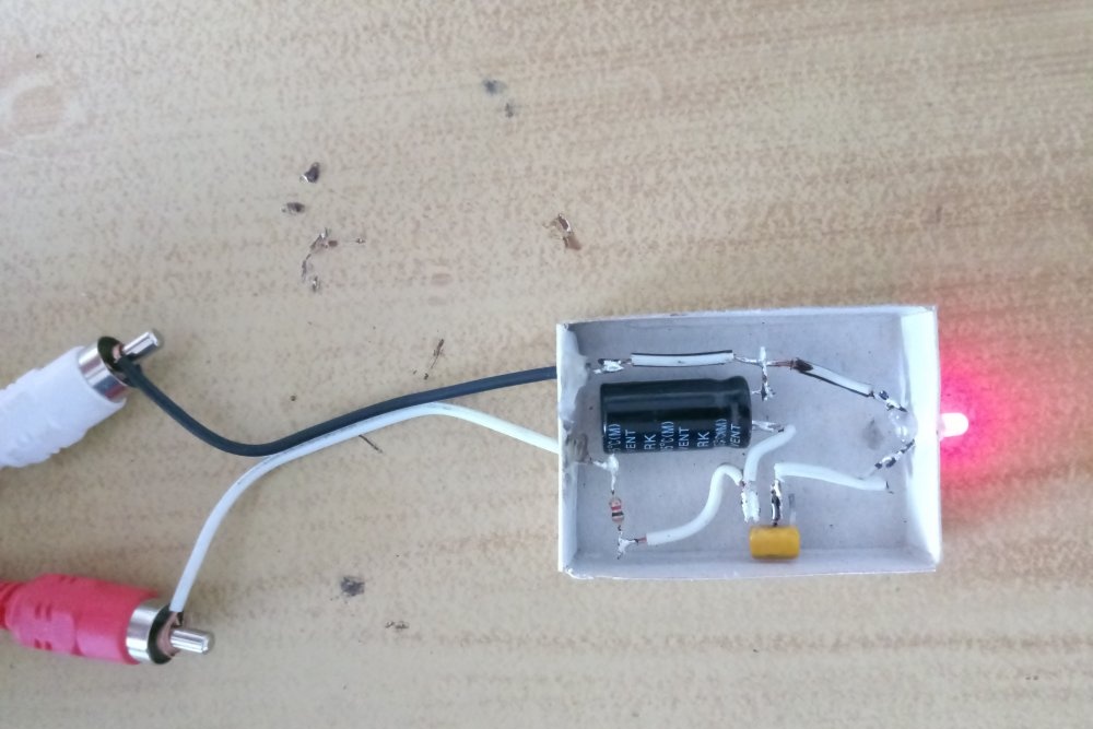
The last component acts as a housing, although the circuit can be assembled without it. Alternatively, a circuit board can be used. The mounted mounting described below is recommended for beginner radio amateurs. This assembly method allows you to quickly navigate the circuit and do everything right the first time.
Flasher assembly sequence
The production of a 12 V LED flasher is carried out in the following sequence. The first step is to prepare all the above components, materials and tools.
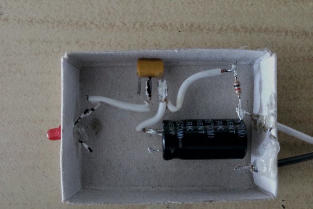
For convenience, it is better to immediately fix the LED and power wires to the case. Next, a resistor should be soldered to the “+” terminal.
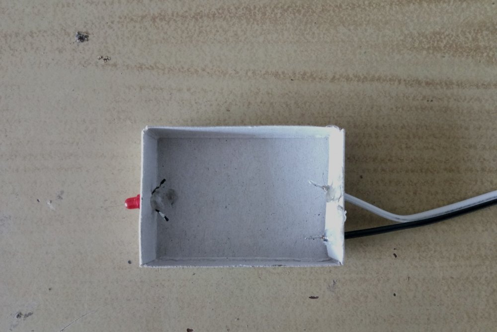
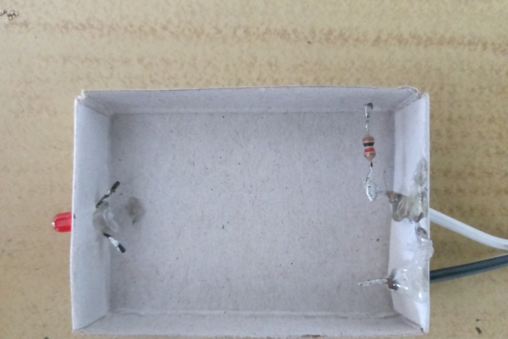
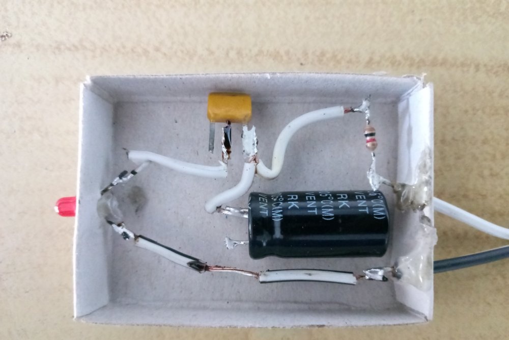
The free resistance leg is connected to the emitter of the transistor. If KT315 is placed with the marking down, then this pin will be on the far right. Next, the emitter of the transistor is connected to the positive terminal of the capacitor.You can identify it by the markings on the case - “minus” is indicated by a light stripe.
The next step is to connect the collector of the transistor to the positive terminal of the LED. KT315 has a leg in the middle. The “plus” of the LED can be determined visually. Inside the element there are two electrodes of different sizes. The one that is smaller will be positive.
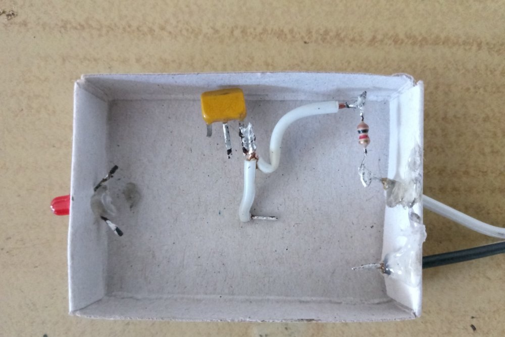
Now all that remains is to solder the negative terminal of the LED to the corresponding conductor of the power supply. The negative of the capacitor is connected to the same line.
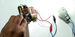
The LED flasher on one transistor is ready. By applying power to it, you can see its operation according to the principle described above.
If you want to reduce or increase the blinking frequency of the LED, you can experiment with capacitors with different capacities. The principle is very simple - the larger the element’s capacity, the less often the LED will blink.
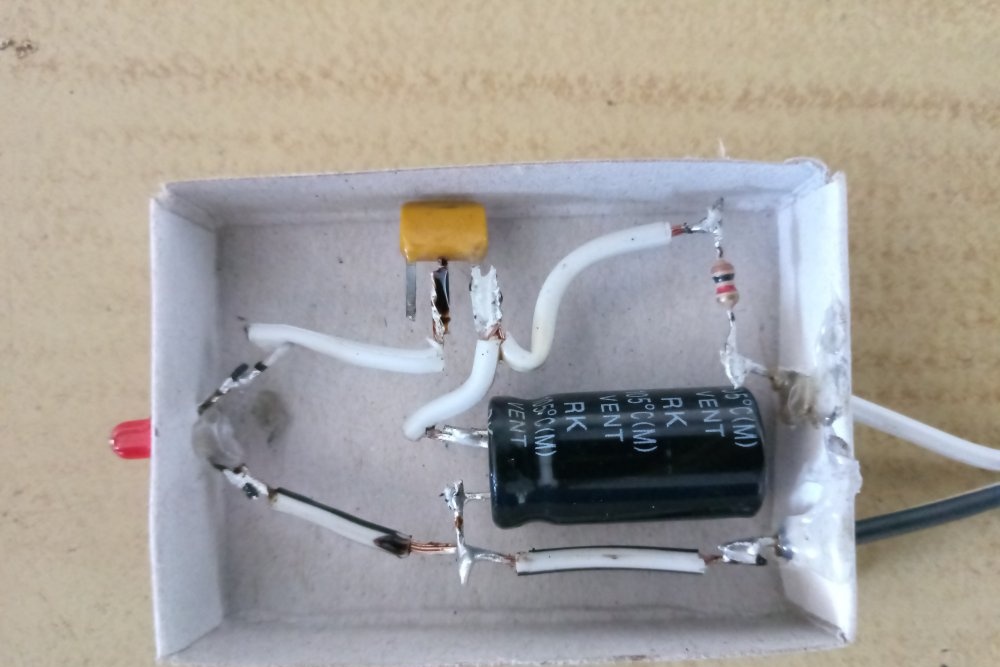
Quite often, even a correctly assembled circuit does not work correctly. If the LED just lights up (does not blink), or does not go out completely, just change the input voltage. On an adjustable power supply, this is done simply by turning the knob in the desired direction. If the power source is unregulated, then you can select the appropriate additional resistance in the circuit.