DIY do it yourself
Master classes, instructions, useful tips, recipes.
» » »Simple battery indicator
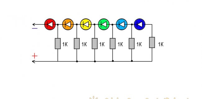
The most amazing thing is that the circuit of the battery level indicator does not contain transistors, or microcircuits, or zener diodes. Only LEDs and resistors are switched on in such a way that an indication of the level of the supplied voltage is provided.

Indicator chart


Battery Level Indicator Diagram

The operation of the device is based on the initial voltage for switching on the LED. Any LED is a semiconductor device that has a voltage boundary point, only exceeding which it starts to work (shine). Unlike an incandescent lamp, which has almost linear current-voltage characteristics, the characteristic of a zener diode is very close to a LED, with a sharp current slope with increasing voltage.
If you turn on the LEDs in the circuit in series with the resistors, then each LED will start to turn on only after the voltage exceeds the sum of the LEDs in the circuit for each segment of the circuit separately.
The threshold voltage of the opening or start of tanning of the LED can vary from 1.8 V to 2.6 V. It all depends on the particular brand.
As a result, each LED lights up only after the previous one lights up.

Battery Level Indicator Assembly


Battery Level Indicator Assembly

I assembled the circuit on a universal circuit board, soldering the output of the elements together. For a better perception, I took LEDs of different colors.
Such an indicator can be made not only on six LEDs, but, for example, on four.
You can use the indicator not only for the battery, but to create an indication of the level on the music speakers. By connecting the device to the output of the power amplifier, parallel to the column. In this way, critical levels for the speaker can be monitored.
It is possible to find other applications of this, in truth, a very simple scheme.
The simplest battery indicator

Watch the video of work and the assembly of the level indicator


come back
Comments (7)
  1. Gregory
    #1 Gregory Guests November 16, 2017 12:25
    0
    The current through the previous LED will increase, with increasing voltage and the subsequent LED. Each subsequent resistor will turn on (via the LED) in parallel to the previous one and the total (total) resistance in the circuit of the first LED will drop sharply, and the current will increase accordingly. Instead of an indicator, this circuit will discharge the battery. After turning on the next LED, the current through the first LED will exceed the maximum permissible current for this LED and it will simply burn.
    1. Dimon
      #2 Dimon Guests November 16, 2017 13:10
      3
      What kind of current does a 1k resistor and an LED need to pass through the circuit so that the LED burns out ??? It needs a lightning strike! So do not tell people !!!
      Everything works great. Although it is better to install the button and periodically turn on and watch the charge.
      The author of the milkweed!
      1. Guest Dmitry
        #3 Guest Dmitry Guests October 14, 2018 16:22
        0
        Tell me, for a lithium battery of 18 volts for 4 LEDs, how to calculate the resistance so that the first LED lights up at 13.5V, 15V 17V, and 20V
  2. Alexey
    #4 Alexey Guests March 27, 2018 14:10
    4
    The scheme does not work in any way as the author intended - it does not show the battery charge. This circuit can only approximately act as a voltmeter.
  3. ali.bar60.
    #5 ali.bar60. Visitors January 25, 2019 11:05
    0
    ... simple, intelligible, unobtrusive !!!
  4. ivan
    #6 ivan Guests February 8, 2019 10:22 p.m.
    0
    and what kind of complaint is this scheme
  5. Guest Alex
    #7 Guest Alex Guests April 17, 2019 17:16
    0
    A much better indicator works from several chains: LED - resistor - zener diode. The ignition voltage can be adjusted by adding silicon or germanium diodes in the forward direction.

Read also

Error codes for washing machines