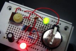
Almost every novice radio amateur assembled a multivibrator using transistors. This circuit does not require a large number of components and has a principle of operation that is quite understandable for beginners. However, the work of the finished product, despite its simplicity, is quite interesting and exciting. Especially if you include two different colored ones in the scheme LED.
Such flashing lights are used in many areas of human activity. The most striking example of the use of the scheme is electronic flashing lights on service vehicles (ambulance, police). Symmetrical multivibrators based on the design described below can also be found in other radio equipment, for example, in sound sirens and alarms. They are used in the simplest children's toys.
Design and principle of operation
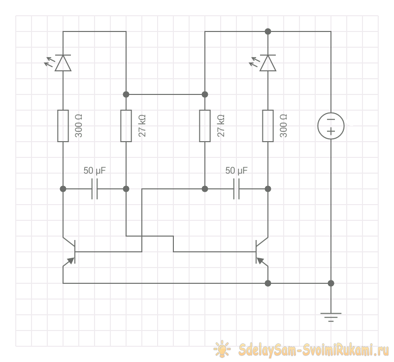
The circuit of a training multivibrator, the step-by-step assembly of which is described below, consists of two transistors, capacitors and LEDs. Additionally, depending on the voltage of the power source used, current-limiting resistors are added to the design.
The flasher operates on two transistors according to the following principle.In the first phase, one of the transistors is in the open state, since current is supplied to its base from the symmetrical arm of the multivibrator. Due to this, one glows Light-emitting diode and the opposite capacitor is charged. This completes the first phase of the cycle.
Further, when the capacitor is fully charged, current stops flowing through it. As a result, the transistor closes and the first Light-emitting diode goes out. Instead, a second one flashes. This happens because the capacitor releases the accumulated energy. At the same time, the second transistor opens and lights up Light-emitting diode. At the same time, the opposite capacitor is charged.
The cycle is then repeated according to the algorithm described above.
Necessary materials and radio components
To assemble a classic 12 V LED multivibrator with your own hands, you will need the following radio components:
- transistors KT361 - 2 pieces (KT315 but you will have to change the polarity of the power supply, capacitors and LEDs);
- electrolytic capacitors with a capacity of 47-50 μF and a nominal value of 16 V - 2 pieces;
- 3 V LEDs - 2 pieces (preferably multi-colored);
- 300 Ohm resistors – 2 pieces;
- 27 kOhm resistors – 2 pieces;
- wires for connecting parts.
To distinguish KT361 transistors from the legendary KT315, just look at their markings. For those needed to assemble a multivibrator according to the above diagram, the letter is located in the middle of the body. KT315 has it in the corner. These parts can be replaced with more modern analogues, for which it is enough to use special resources on the Internet. You can, of course, use KT315, but in this case the polarity of the power supply, capacitors, and LEDs will need to be swapped.
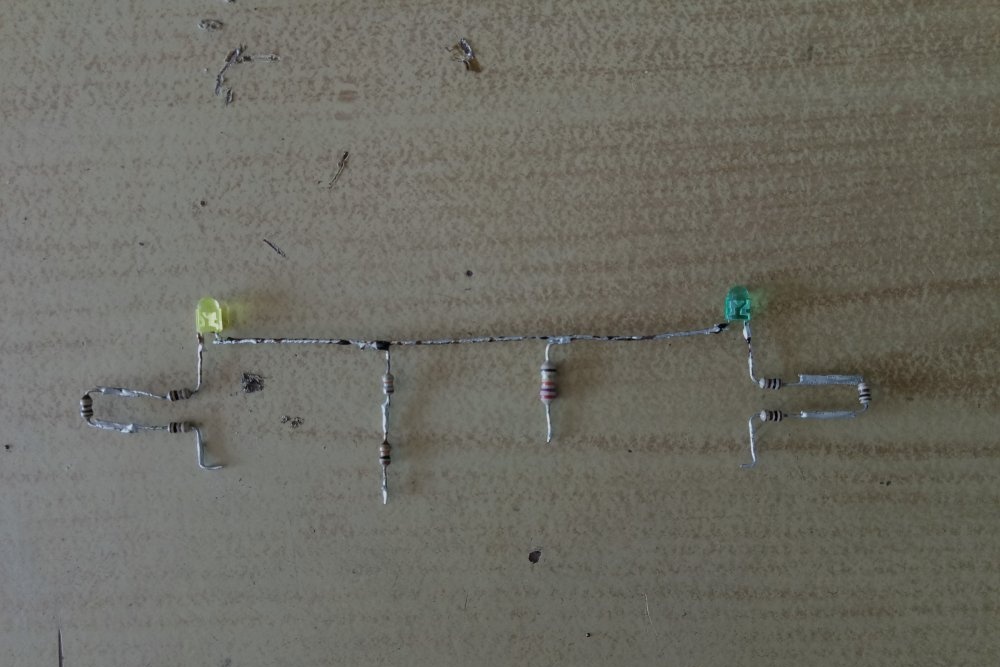
If resistors with the indicated values are not at hand, then you can take several pieces with lower resistance. By connecting them in series (as in the photographs), we obtain the required parameters. Please note that with a power source with a different voltage (9 V or 4.5 V), parts with a lower rating will be needed.
Capacitors can be taken with a different capacity. This will directly affect the blinking frequency of the LEDs. The larger the capacitance, the lower the switching frequency. The capacitor rating must be greater than the voltage of the power source used.
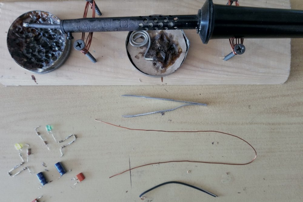
Naturally, to successfully assemble a symmetrical multivibrator circuit, you will also need a minimum soldering kit.
Step-by-step assembly of a multivibrator
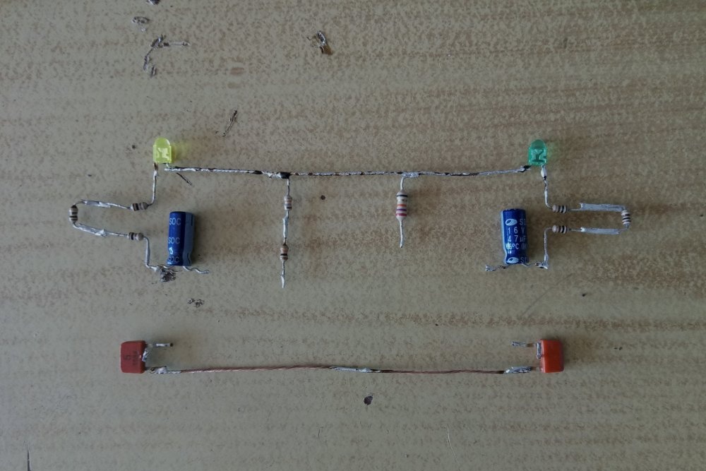
To begin with, it is recommended to collect all the necessary radio components and lay them out on the table as shown in the diagram. If soldering is carried out on the board, then this step can be skipped. When assembling a multivibrator with a surface-mounted installation, the sequence of actions will be as follows.
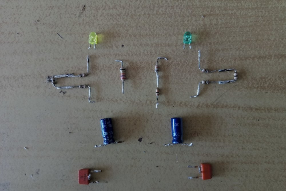
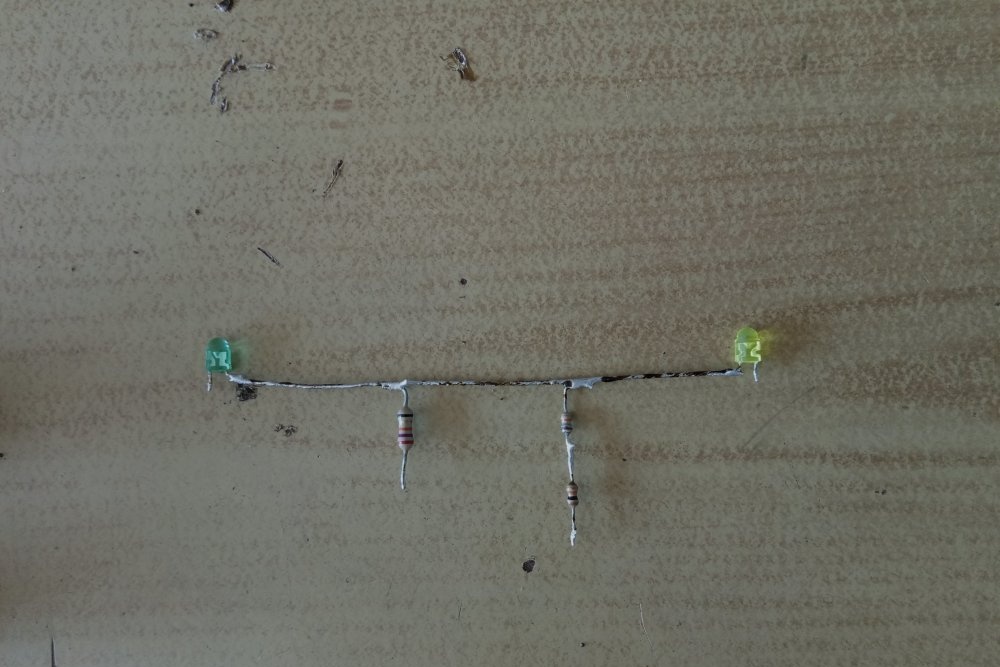
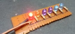
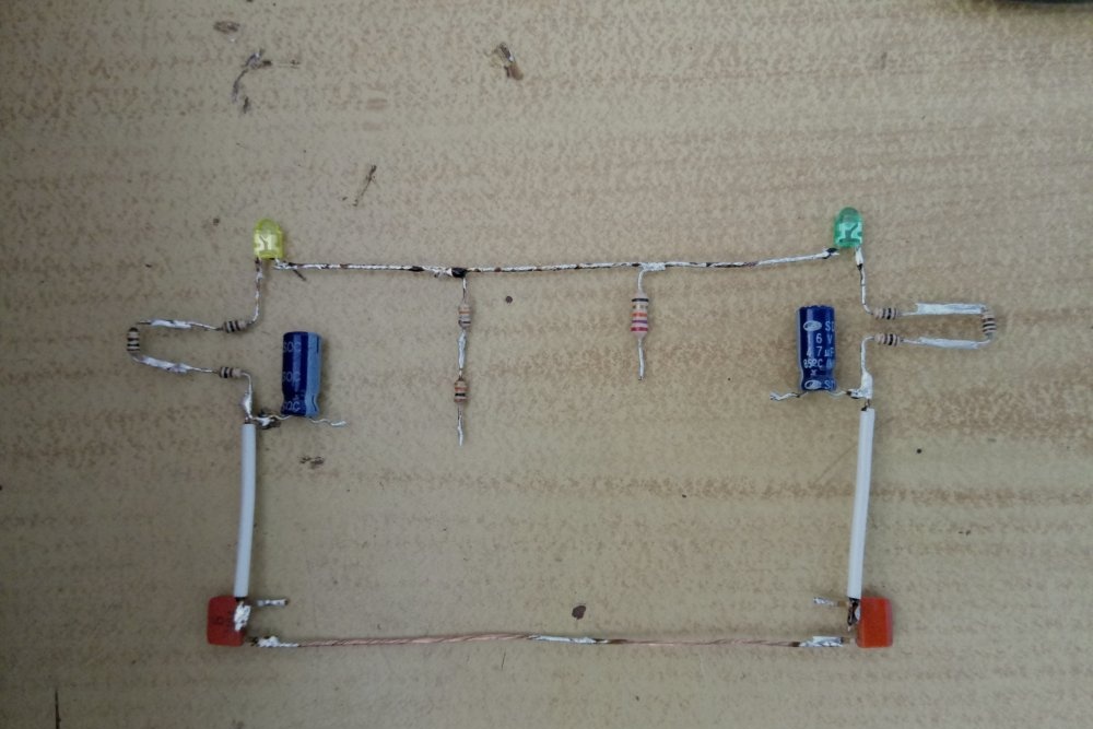
First, the LEDs are connected to each other, and a main resistance of 27 kOhm is added to the circuit. In this case, the polarity of the light sources is taken into account. With classic LEDs, the negative terminal is visible upon visual inspection of the element - inside it is significantly wider than the positive one. It is the “negative” legs that are soldered together. Resistors are mounted between the LEDs as shown in the photo.
Next, 300 Ohm resistors are soldered to the positive terminals of the LEDs. They are needed in order to limit the current and protect the elements from combustion.
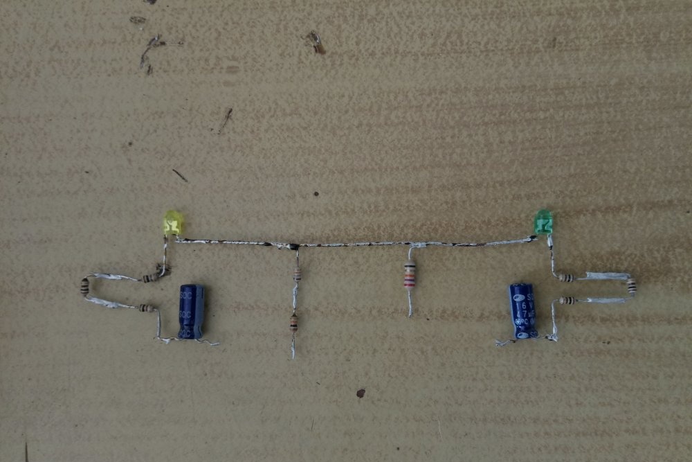
Next is the turn for electrolytic capacitors. It is worth remembering that they also have positive and negative conclusions.The “minus” can usually be seen on the case - it is marked with a light stripe and corresponding symbols. At this stage of assembly we need positive leads - they are soldered to 300 Ohm resistors, as shown in the photo.
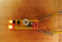
The most complex parts in this circuit (for beginner radio amateurs) are the transistors. To simplify installation and not confuse anything, it is recommended to immediately arrange the elements as shown in the photo. We turn the transistor of the left shoulder of the multivibrator with the letter marking up, and the right one - down.
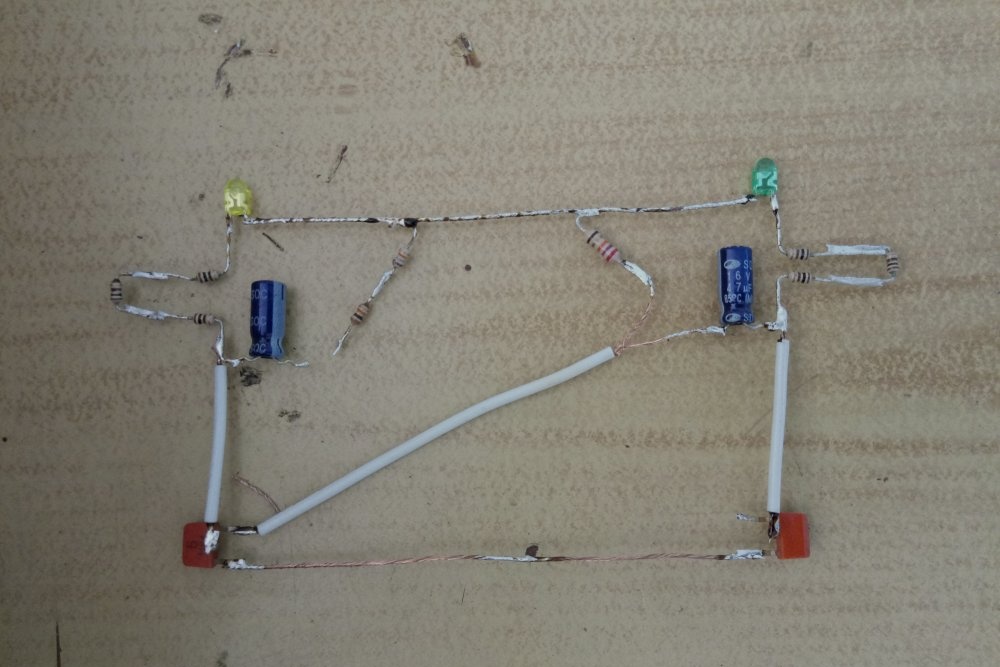
With this arrangement, the lower legs directed towards each other will be emitters. They need to be connected to each other. Power with a “plus” sign will be supplied to the same area.
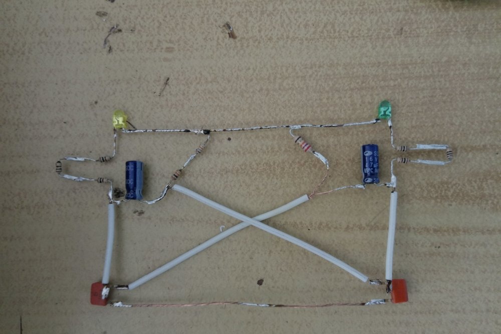
Next, you need to connect the collectors of the transistors to the positive terminals of the capacitors. For convenience, it is recommended to bend the middle legs of the parts accordingly (for KT361 these are the collectors).
The last step is to connect the bases of the transistors with the negative terminals of the capacitors from the opposite arms of the multivibrator. The resistances that were previously mounted in the circuit (at 27 kOhm) are also connected to the soldering points of these units. With this positioning, the bases of both transistors will be on top, which will also make working with them easier.
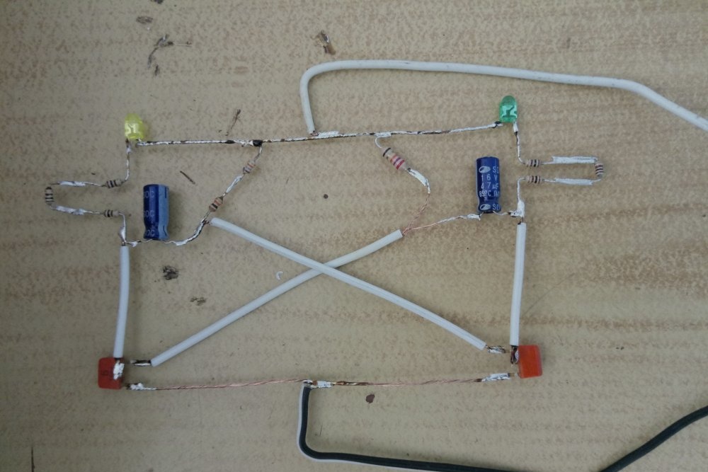
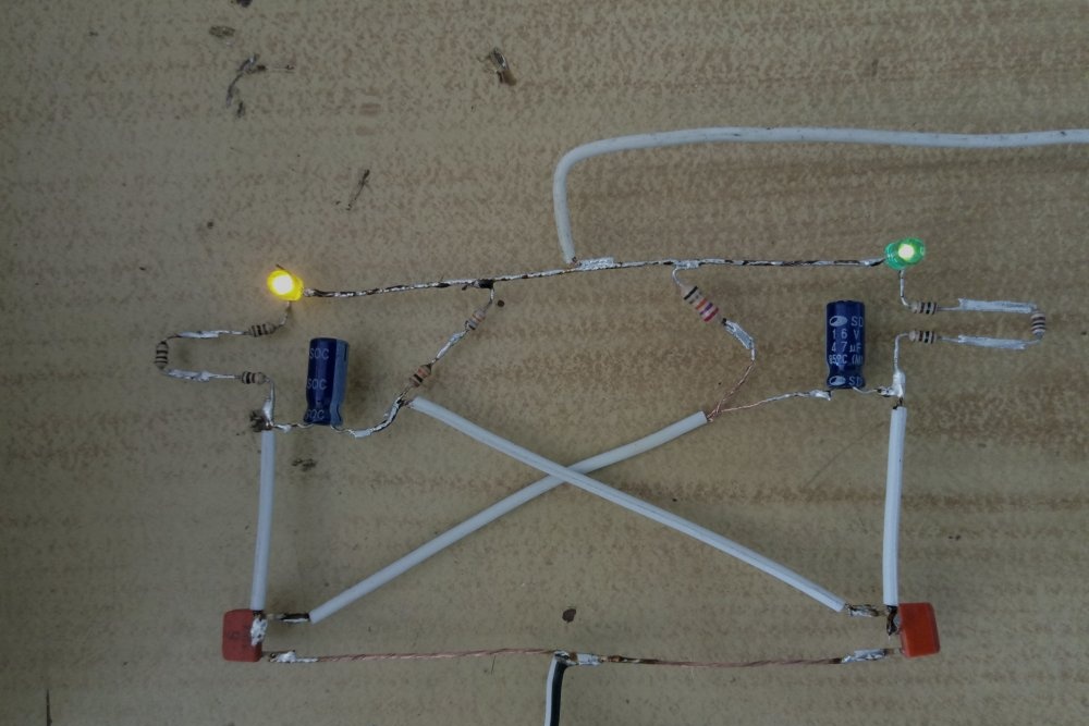
Now all that remains is to connect the wires from the power supply. The positive terminal is soldered to the connection line of the emitters of the transistors, and the negative terminal is soldered between the LEDs. When you turn on the power supply, the multivibrator should immediately start working without any additional settings.
If the LEDs do not go out completely when turned off, then a small current-limiting resistor can be added to the beginning of the circuit.If the power supply is adjustable, just turn down the voltage a little and everything will work.