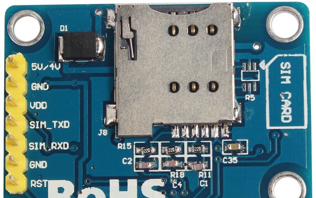
SIM800L V2.0 GSM / GPRS is a quad-band GSM / GPRS module compatible with Arduino. The module is used to implement the functions of GSM (calls and SMS) and GPRS. The advantage of this module is the TTL interface with a voltage of 5V, which allows you to directly connect it to an Arduino or any other system with a 5V power supply. Most GSM / GPRS modules on the market require regulator connections or level conversion, while in SIM800L V.2 GSM / GPRS does not require additional interface level conversion circuits.
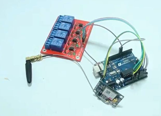
Here is an example project using SIM800L V.2 GSM / GPRS. The meaning of the project is to control the switches using the SMS controller. You can easily turn on and off most household appliances in the house, such as a llama, a fan, and so on.
Characteristics of the SIM800L V.2 GSM / GPRS module
Below are all the technical specifications of the SIM800L V.2 GSM / GPRS module:
- TTL serial interface compatible with 3.3V and 5V microcontrollers compatible with Arduino.
- The SIM800L module has a TTL serial interface.
- Antenna plug
- Network support: four bands 850/900/1800/1900 MHz, capable of making calls, SMS and data transfer with significantly reduced battery consumption.
- VDD TTL UART interface, so you can directly connect an MCU such as 51MCU, ARM or MSP430. VDD plug used to match TTL voltage.
- Model: SIMCOM SIM800L
- Working voltage: from 3.7V to 5V;
- dimensions: 40mm x 28mm x 3mm
- GPRS multislot class 12/10
- GPRS Batch Service Class B
- Corresponds to GSM phase 2/2 +
- Class 4 (2 Watts @ 850/900 MHz)
- Class 1 (1 Wat @ 1800/1900 MHz)
Necessary materials
You'll need:
1. .
2. .
3. .
4. .
5. .
(Active links to the store for purchase)
Assembly and configuration
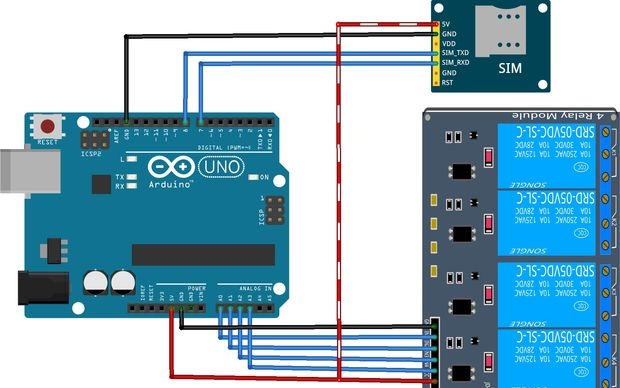
Once you have connected all the components, create a program, and then download it to your Arduino. But first, you must install the GPRS library, which you can download:
[28.02 Kb] (downloads: 481)
Program Code for Arduino

After you have connected your SIM800L, 4-channel relay module and Arduino to your computer, enter the code below and you're done.
#include
#include
#define TIMEOUT 5000
#define ACTIVE LOW
#define OFF HIGH

byte Relay [] = {A0, A1, A2, A3};
byte StatRelay [4];
char buffNumber [20];
char currentLine [500] = "";
int currentLineIndex = 0;
bool nextLineIsMessage = false;
String replyNumber = "089510863958";
GPRS gprs;

void setup () {
for (int i = 0; i <4; i ++) {
pinMode (Relay [i], OUTPUT);
digitalWrite (Relay [i], MATI);
StatRelay [i] = MATI;
}

Serial.begin (9600);
while (! Serial);
Serial.println ("Activate SIM800L V2 >>> Automatically Read SMS");
gprs.preInit ();
delay (1000);
while (0! = gprs.init ()) {
delay (1000);
Serial.print ("init errorrn");
}

// Manage message to mode ASCII
if (0! = gprs.sendCmdAndWaitForResp ("AT + CMGF = 1rn", "OK", TIMEOUT)) {
ERROR ("ERROR: CNMI");
return
}
// Read Incoming SMS
if (0! = gprs.sendCmdAndWaitForResp ("AT + CNMI = 1,2,0,0,0rn", "OK", TIMEOUT)) {
ERROR ("ERROR: CNMI");
return
}
int pjg = replyNumber.length () + 1;
buffNumber [pjg];
replyNumber.toCharArray (buffNumber, pjg);
Serial.print ("Send reply to number =>");
Serial.println (buffNumber);
Serial.println ("Initialization Done");
Serial.println ("============================================= ================= ");
}

void loop () {
// Change status Relay ON / OFF
for (int i = 0; i <4; i ++) {
digitalWrite (Relay [i], StatRelay [i]);
}

// If there is input data from SIM800
if (gprs.serialSIM800.available ()) {
char lastCharRead = gprs.serialSIM800.read ();

// Save all data on lastCharRead, then if there is r or n, as a final signal of incoming message
if (lastCharRead == 'r' || lastCharRead == 'n') {
String lastLine = String (currentLine);

// If the last message + CMT indicates new message arrive
if (lastLine.startsWith ("+ CMT:")) {
Serial.println (lastLine);
nextLineIsMessage = true;
} else if (lastLine.length ()> 0) {
if (nextLineIsMessage) {
Serial.println (lastLine);

// ================================================= ================== >> Function of Relay Controller

// Relay 1 Controller

if (lastLine.indexOf ("Relay 1 ON")> = 0) {
StatRelay [0] = AKTIF;
Serial.print ("Reply ==== >>>>");
Serial.println ("Relay 1 Status Active");
gprs.sendSMS (buffNumber, "Relay 1 Status Active");
}

else if (lastLine.indexOf ("Relay 1 OFF")> = 0) {
StatRelay [0] = MATI;
Serial.print ("Reply ==== >>>>");
Serial.println ("Relay 1 Status Off");
gprs.sendSMS (buffNumber, "Relay 1 Status Off");
}

// Relay 2 Controller

if (lastLine.indexOf ("Relay 2 ON")> = 0) {
StatRelay [1] = AKTIF;
Serial.print ("Reply ==== >>>>");
Serial.println ("Relay 2 Status Active");
gprs.sendSMS (buffNumber, "Relay 2 Status Active");
}
else if (lastLine.indexOf ("Relay 2 OFF")> = 0) {
StatRelay [1] = MATI;
Serial.print ("Reply ==== >>>>");
Serial.println ("Relay 2 Status Off");
gprs.sendSMS (buffNumber, "Relay 2 Status Off");
}

// Relay 3 Controller
if (lastLine.indexOf ("Relay 3 ON")> = 0) {
StatRelay [2] = AKTIF;
Serial.print ("Reply ==== >>>>");
Serial.println ("Relay 3 Status Active");
gprs.sendSMS (buffNumber, "Relay 3 Status Active");
}
else if (lastLine.indexOf ("Relay 3 OFF")> = 0) {
StatRelay [2] = MATI;
Serial.print ("Reply ==== >>>>");
Serial.println ("Relay 3 Status Off");
gprs.sendSMS (buffNumber, "Relay 3 Status Off");
}

// Relay 4 Controller
if (lastLine.indexOf ("Relay 4 ON")> = 0) {
StatRelay [3] = AKTIF;
Serial.print ("Reply ==== >>>>");
Serial.println ("Relay 4 Status Active");
gprs.sendSMS (buffNumber, "Relay 1 Status Active");
}
else if (lastLine.indexOf ("Relay 4 OFF")> = 0) {
StatRelay [3] = MATI;
Serial.print ("Reply ==== >>>>");
Serial.println ("Relay 4 Status Off");
gprs.sendSMS (buffNumber, "Relay 4 Status Off");
}
nextLineIsMessage = false;
}

// ================================================= ==================== >>

}
// Clear char array for next line of read
for (int i = 0; i
Device check
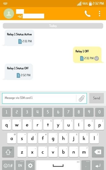
The tool works by sending SMS to SIM800L with a specific sequence of characters. For example, to enable relay 1, use the “Relay 1 ON” command, and to turn it off, use the “Relay 1 OFF” command. The rest of the relays have almost the same commands, with the exception of the serial number of each relay that you want to act on. After automatically sending a message, the SIM800 will send a response in the form of a status message for each SIM card.