Digital multimeters are very popular among radio amateurs and professionals due to their versatility. To power them, as a rule, a nine-volt Krona battery is used, which has noticeable self-discharge, low capacity and a higher price compared to other elements.
Suggested digital power supply multimeter from one AA element with a voltage of 1.5 volts, will avoid these operational shortcomings and simplify the operation of the device.
There are many different circuits offered on the Internet for converting 1.5 to 9 volts. Each has its pros and cons. This device is made on the basis of A. Chaplygin’s circuit, published in the magazine “Radio” (11.2001, p. 42).
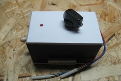
The difference between this version of the converter is the location of the battery and voltage converter in the cover of the case multimeter, instead of creating a compact power supply installed instead of the Krona battery.This allows you to replace the AA element at any time, without disassembling the device, and, if necessary, turn off the converter (Jack 3.5 connector) with automatic activation of the Krona backup battery located in its compartment. In addition, when manufacturing a voltage converter, there is no need to miniaturize the product. It’s faster and easier to wind the transformer on a ring with a larger diameter, better heat dissipation, and a freer circuit board. This arrangement of components in the cover of the case does not interfere with working with the multimeter.
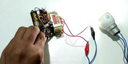
This converter can be made in any suitable housing and used in a wide variety of devices that require power from a nine-volt Krona battery. These are multimeters, watches, electronic scales and toys, medical devices.
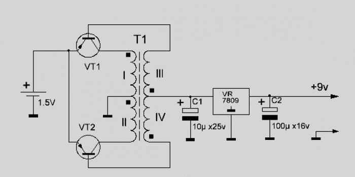
Voltage converter generator circuit
A DC boost inverter is proposed that has good output data with a minimum of input elements.
The diagram is shown in the figure.
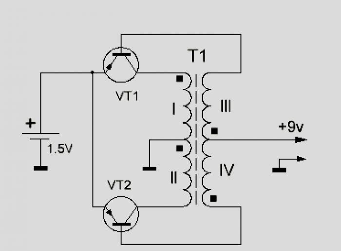
A push-pull pulse generator is assembled using transistors VT1 and VT2. The positive feedback current flows through the secondary windings of transformer T1 and the load connected between the + 9 V circuit and the common wire. Due to proportional current control of transistors, switching losses are significantly reduced and the efficiency of the converter is increased to 80... 85%.
Instead of a high-frequency voltage rectifier, base-emitter junctions of the transistors of the generator itself are used. In this case, the value of the base current becomes proportional to the value of the load current, which makes the converter very economical.
Another feature of the circuit is the interruption of oscillations when there is no load, which can automatically solve the power management problem.Almost no current is consumed from the battery when there is no load. The converter will turn on itself when it is required to power something and turn off when the load is disconnected.
But since most modern multimeters have an automatic power-off function, to avoid modification of the circuit multimeter, it is easier to install the inverter power switch.
Manufacturing of voltage converter transformer
The basis of the pulse generator is transformer T1.
The magnetic core of transformer T1 is a K20x6x4 or K10x6x4.5 ring made of 2000NM ferrite. You can take a ring from an old motherboard.
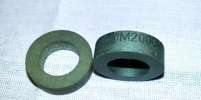
1. First you need to prepare the ferrite ring.
- To prevent the wire from cutting through the insulating gasket and damaging its insulation, it is advisable to dull the sharp edges of the ferrite ring with fine-grained sandpaper or a needle file.
- Wrap an insulating pad around the ring core to prevent damage to the wire insulation. To insulate the ring, you can use varnished cloth, electrical tape, transformer paper, tracing paper, lavsan or fluoroplastic tape.

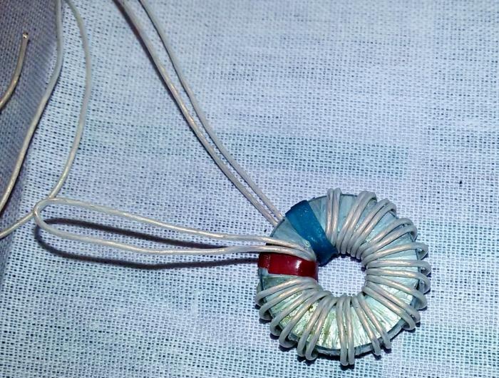
2. Winding of transformer windings with a transformation ratio of 1/7: primary winding - 2x4 turns, secondary winding - 2x28 turns of insulated wire PEV -0.25.
Each pair of windings is wound simultaneously into two wires. Fold the wire of the measured length in half and with the folded wire begin to tightly wind the required number of turns onto the ring.
To avoid damage to the wire insulation during operation, if possible, use MGTF wire or other insulated wire with a diameter of 0.2-0.35 mm.This will slightly increase the dimensions of the transformer and will lead to the formation of a second winding layer, but will guarantee uninterrupted operation of the voltage converter.
- First, the secondary windings lll and lV (2x28 turns) of the transistor base circuit are wound (see converter diagram).
- Then, in the free space of the ring, also in two wires, the primary windings l and ll (2x4 turns) of the transistor collector circuit are wound.
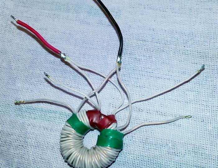
- As a result, after cutting the loop of the beginning of the winding, each of the windings will have 4 wires - two on each side of the winding. We take the wire from the end of one half of the winding (l) and the wire from the beginning of the second half of the winding (ll) and connect them together. We proceed similarly with the second winding (lll and lV). It should look something like this: (red terminal is the middle of the lower winding (+), black terminal is the middle of the upper winding (common wire)).
- When winding the windings, the turns can be secured with glue “BF”, “88” or colored electrical tape indicating the beginning and end of the winding in different colors, which will later help to correctly assemble the transformer windings.
- When winding all coils, you must strictly observe one winding direction, and also mark the beginning and end of the windings. The beginning of each winding is marked on the diagram with a dot at the terminal. If the phasing of the windings is not observed, the generator will not start, since in this case the conditions necessary for generation will be violated. For the same purpose, as an option, it is possible to use two different-colored wires from the network cable.
Voltage converter assembly
For operation in low-power converters, as in our case, transistors A562, KT208, KT209, KT501, MP20, MP21 are suitable. You may have to select the number of turns of the secondary winding of the transformer.This is due to the different magnitude of the voltage drop across p-n junctions for different types of transistors.
Transistors should be selected based on the permissible values of the base current (it should not be less than the load current) and the emitter-base reverse voltage. That is, the maximum permissible base-emitter voltage must exceed the required output voltage of the converter.
In order to reduce noise and stabilize the output voltage, the converter is supplemented with a unit of two electrolytic capacitors (to smooth out voltage ripples) and an integrated stabilizer 7809 (with a stabilization voltage of 9 volts) according to the scheme:
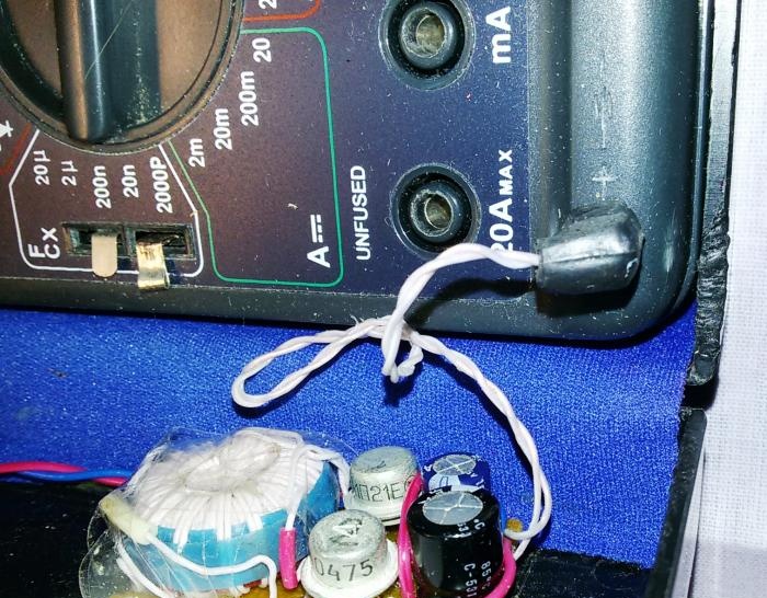
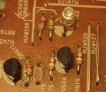
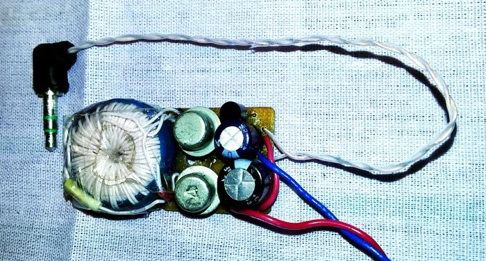
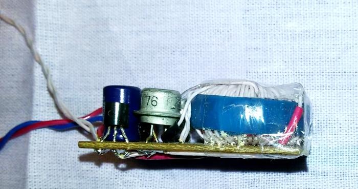
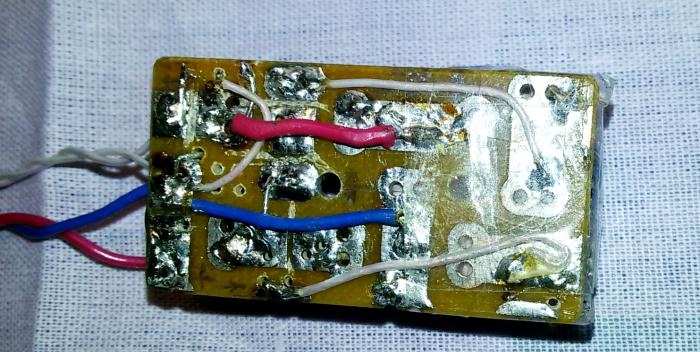
We assemble the converter according to the diagram and solder all the incoming elements on a textolite board cut from a universal circuit board sold in radio products using the surface-mounting method. The dimensions of the board are selected depending on the sizes of the selected transistors, the resulting transformer and the installation location of the converter. The input, output and common bus of the converter are led out by a flexible stranded wire. The output wires, with a voltage of +9V, end with a 3.5 Jack connector for connecting to a multimeter. The input wires are connected to a cassette with a 1.5 volt battery installed.
The AA battery (1.5V) is installed in a double cassette from a portable receiver.
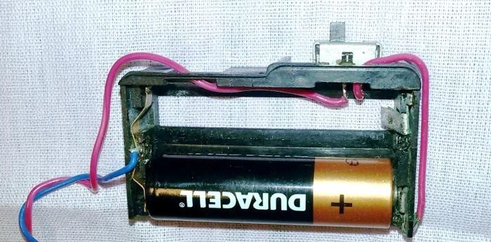
One place is occupied by the battery, the other place is used to install the power switch and secure the entire cassette, through an adapter textolite strip, in the case multimeter.
Setting up the converter.
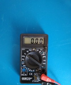
We check that the converter is assembled correctly, connect the battery and use the device to check the presence and magnitude of voltage at the converter output (+9V).
If generation does not occur and there is no voltage at the output, check that all coils are connected correctly.The dots on the converter diagram mark the beginning of each winding. Try swapping the ends of one of the windings (input or output).
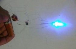
The converter is capable of operating when the input voltage is reduced to 0.8 - 1.0 volts and receives a voltage of 9 volts from one galvanic element with a voltage of 1.5 V.
Refinement of the multimeter
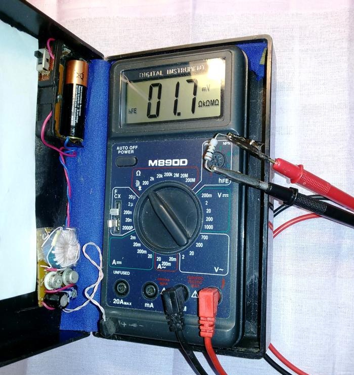
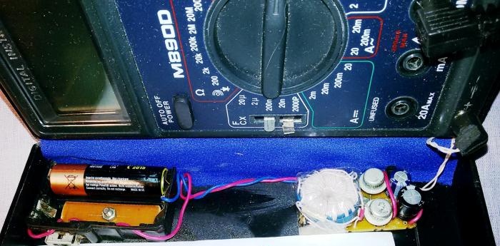
To connect the converter to the multimeter, you need to find a free space inside the device and install a socket there for a 3.5 Jack plug or a similar available connector. In my M890D multimeter, there was free space in the corner, to the left of the Krona battery compartment.
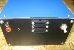
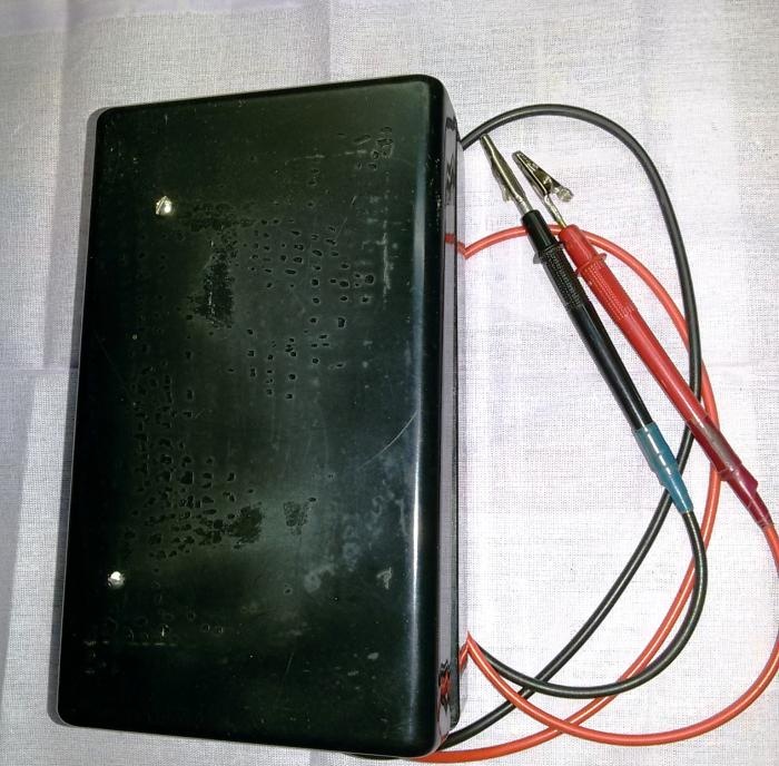
As a case for multimeter An electric razor case is used.