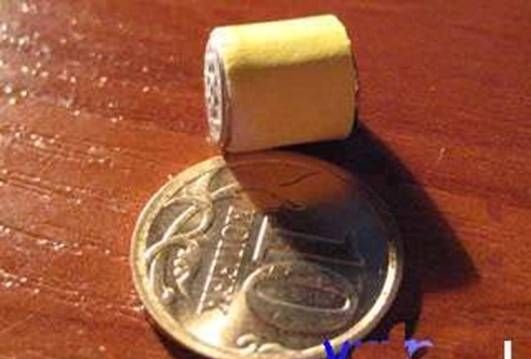
Miniature Exam Devices
CONTENT
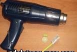
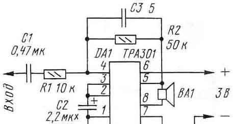
Small Exam Transceiver
Do-it-yourself miniature earphone
Wireless Exam Earphone-1
Exam 2 Wireless Earphone
Wireless micro-earpiece on a chip
Hidden Carrying Wireless Earphone
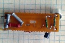
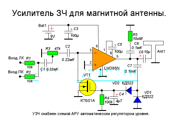
This transceiver is one of my first developments. I don’t remember, before or after the movie “Operation Y”, I assembled a portable transceiver and with it successfully passed just one exam - “Scientific Communism.” All other exams did not cause problems .... And a classmate Zilberstein dictated to me from the synopsis ( maybe respond?).
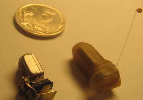
Powered by a Krona battery. R6 volume control with a switch from a handheld receiver. A range of several tens of meters covered the entire Institute of Communications (OEIS). An antenna from a flexible wire 1-1.5 meters was placed under a jacket on the back. Capsule ДЕМШ1А is connected cable in the screen, passed into the sleeve and placed under the bracelet of the watch. Putting it into a fist, he whispered the ticket topic, and propping his ear barely had time to write down. Switch S1, the French prototype P2K, was turned on by pressing the elbow on the trouser pocket.
So here she came the session and the "hell", i.e. teacher with a bucket of nails and strives to hammer them in your ass. No, I will not offer the original design of the nail clipper. Let's talk about how to avoid the most unpleasant process of driving “nails” using modern technologies. It was invented by me back in '96, when I was in my first year at a university. Well, actually, I’ve been unlearned for 5 years and went out as a specialist with a clear conscience and an empty head :-). Paleva has never been. It was a preamble, so to speak.
So we need:
1. superglue
2. A powerful magnet from a computer hard drive.
3. used finger battery.
4. relay RES-10 in a disassembled state from which we need a thin wire. Other relays will do. The main thing is a thin wire. The thinner the better.
5. fiberglass foil.
6. dead Chinese earphone. he needs only a membrane.
7. the used rod from the fountain pen with a diameter of 2.5 - 3 mm and two washers that would fit onto it and not jump off.
Technology
We take the finger battery and remove the tin shirt from it. From this sheet we cut a strip 22-25 mm long and 3-4 mm wide. Then we bend it so that we get a cylinder. Solder the seam of the cylinder. This is the base of the earphone.
Now you can start making the base. To do this, fiberglass is taken with a thickness of about 0.3-0.5 mm (if necessary, it is well delaminated) and a circle of the desired diameter is cut out of it, it must enter the case with effort. Alternatively, you can etch the entire pattern in advance, and then cut everything with scissors. You can also cut through all the contact pads with a cutter knife. At the edge of the circle, the fiberglass is soldered to the base of the cylinder. On this case is ready.
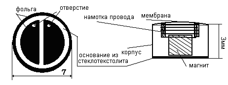
Now you need to glue the magnet to the base. A simple magnet will not roll here, you need a very powerful one and it is extracted from the crumbled hard drives. One magnet from there is enough for a lot of headphones. The magnet mined from the holiest place on the computer crumbles !!! nippers into cubes the size according to the scale (2x2x2 mm) of the figures.One of the resulting cubes (cubes for the first time are obtained after about 10-20 minutes of crumbling) is glued !!!!!! attention !!!!!! southern !!!! or !!!!! North !!! pole to the base. Determine where which pole can be using any magnet from a broken-down Chinese headphone. They are glued with superglue. The main thing is not to seal the two holes on the base.
The membrane is extracted from Chinese headphones (and the more Chinese the earphone the better, because the membrane is thinner "it seems to me that they even save polyethylene" because the excessive rigidity of the membrane affects the volume of the headphone). The wire for the coil is extracted from a relay of the RES-10 type. The coil is wound on the shaft of the pen D = 2.5mm so that the winding does not creep onto the shaft and the washer-limiters are put on. A hole is made in the rod into which one end of the wire is poked. Before starting winding for the first time, you should practice and reel several test coils, they should not be very large because can further cling to the magnet. The resistance of the coil should be in the range of 20-80 ohms, this is about 80 or more turns. When winding, the wire is slightly wetted with a “moment” or BF, you can also use superglue, but carefully so that the coil does not fall apart later when you take it off. Immediately after winding, it is removed so that it does not dry out, but if it does dry and stick, you can use alcohol that quickly dissolves the moment. After several unsuccessful attempts to remove the coil from the frame and not damage, it must be glued to the membrane !!!!!!!!!!! using at the same time a minimum of superglue. In no case do you apply superglue to the membrane in places where it does not come in contact with the coil - otherwise the membrane will become stiff and the earphone will work quietly. Tin coil wiring at a distance of 2 mm from it.
Now, having inserted the wiring of the coil into the holes of the base, the membrane is glued with a minimum of superglue to the outer side of the cylinder body. The wires are soldered to the pads. In this case, it is necessary to make every effort not to overheat the headphone; otherwise, a magnet or something else may fall off. Now ring with an ohmmeter and make sure that everything is in order 20-80 Ohms.
Wireless headphone for exams
(Option 1)
This device was not assembled out of necessity, but because of the absence of its circuit in the network.
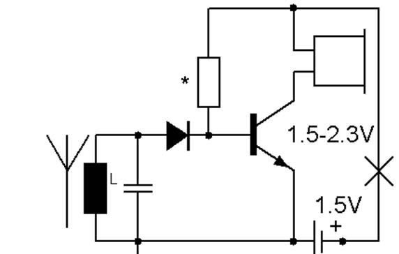
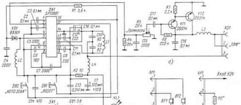
The receiver of the device is simple. It is a detector receiver with one cascade of amplification. The input circuit is composed of a resistor and a capacitor, the voltage induced in the circuit is detected by a diode and then amplified by a transistor in the collector of which a high-impedance earphone is installed and it is a load; -430k ohm. Such a simple construction of the circuit provides high parameters at very small sizes. The transistor used by the domestic KT3130 when choosing a transistor should seek to maximize its amplification. The diode was taken flint with a shotka barrier type KD514 or similar imported! Of course, it was better to use germanium, but they could not be found miniature. Resistor RC0402 5% from 200 to 430ohm (select when tuning to the maximum undistorted signal. Any SMD inductor is suitable for the receiver circuit. I used 1 µkH type SDR0402 type / size 0402 from Bourns. SMD capacitor type GRM size 0402 +/- 5% TKE MP0 39 picoforad capacity which corresponds to approximately 25 MHz in the loop Earphone type TEM-1957, TEM-1956, TEM-1958M, TEM-1958, TEM 2632 or any miniature main thing is that its resistance is at least 300 Ohms better even higher. choose the smallest possible one from electronic wristwatches, but no trace Let’s forget that the smaller it is and the cheaper you get it, the less it will last! Perhaps it will not last until the end of the exam. For lack of miniature headphones I can’t lay out the entire design of the headphone, although it’s not difficult to guess, but soon they should Then the article will appear much fuller and not expensive sets for self-assembly will appear!
Transmitter.
The circuit is quite simple; it's just an AM modulated transmitter tuned to a frequency of 25 MHz. It consists of a sound frequency amplifier modulator and the high frequency generator itself.
At the base of the transistor T4, a bias voltage must be supplied through the resistor, it is passed in the circuit. 180 kΩ resistor from power plus to T4 transistor base
VLF (T 1) and modulator (T 3) do not need tuning. Setting the master oscillator is carried out by changing the position of the trimmer of the common coil L 1, L 2 and changing the values of the capacitors C 6 to the maximum of the wave meter. The next stage is L 3. It may be necessary to select the values of the base resistor 24kom (the transistor current of the master oscillator). When tuning the antenna using changes in the capacitors of the P-filter and tuning L 5 it is advisable to use a wave meter. When adjusting the output stage and matching it with the antenna, it is advisable to take into account not the optimality of its length, which reduces the radiated power of the transmitter. Therefore, it is advisable (as in the previous case) to use additional inductance (although this is not mandatory), increasing the effective length of the transmitting antenna of the transmitter. This coil is connected in series with the antenna (not shown in the diagram). The parameters of the elements of the U-shaped filter (L 5) and the additional coil coincide with the parameters of the previous design.
Here is another update, the working scheme, but in practice has not been applied yet.
Wireless headphone for exams
(Option 2)
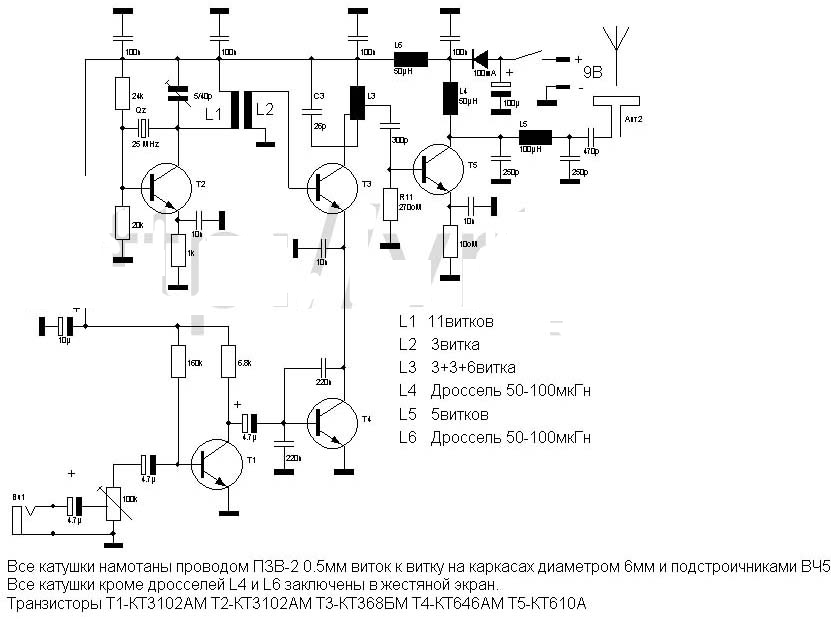
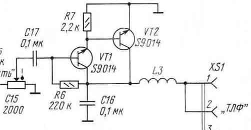
This radio earphone differs from Option 1 in all its principle of operation. It works using an inductive method. The coil that will be on your neck is the primary winding, and on the earphone it is secondary. All other electronics are low-frequency amplifiers. Now by design.
On the TEM-1958 headphone we wind the receiving coil, it contains 70-100 turns of enameled wire type PEV-2 0.05-0.07 thicker should not be used (it may not fit into the ear). You can see the radio parts used in the radio headset, see fig. one
Fig. one
All parts of the earphone can be mounted in two ways. The first is the easiest. It is a hinged installation. 2 and 3
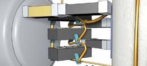
Fig. 2
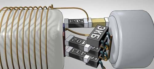
Fig. 3
Now let's dwell on the headphone circuit. It is assembled quite primitive and does not need any sort of adjustment if assembled from pre-operational components. Scheme see fig. four.
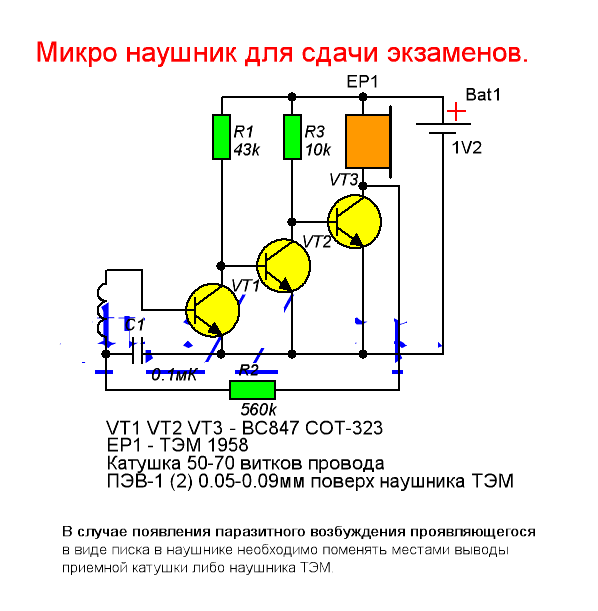
Fig. four
As can be seen from the diagram, this is a conventional low-frequency amplifier with direct connection (s); the coil is connected through an isolation capacitor. All transistors in our version were selected by the enemy mainly because of the miniature case type SOT-323, they are called BC847. You can apply any other low-power sound even the structure does not matter only the size. (If you change the structure of the transistors, simply change the polarity of the power supply of the device.)
Transmitter Antenna (see Fig. 5)
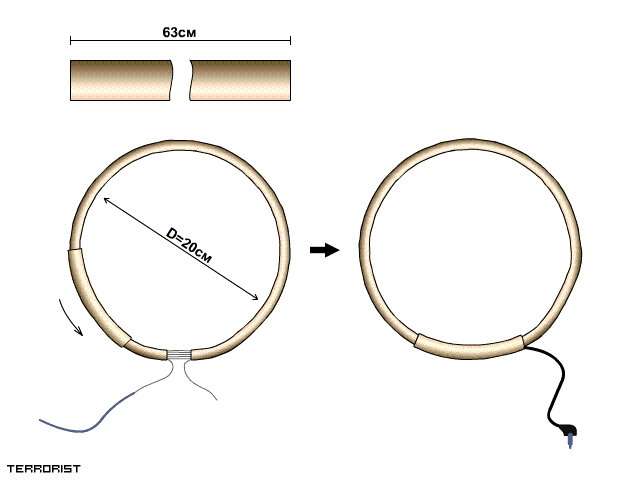
It is simple to make. A wire with a diameter of 0.33 mm or so. It’s better to take a flexible mounting, the softer the better. You also need a heat shrink tube that is close to the color of your clothes or body. But this is not necessarily possible just in faded tones. On a mandrel (pot pan or something else) 20 cm in diameter, measure the shrink tube by bending and cut it off. We do the same, I pass a rocky wire about 1-2 mm thick into the terma tube and tie our wire to one end of it with any convenient method. This will be an impromptu needle. Now we measure a piece of wire, measuring its resistance, it should be about 16nn. Now we begin to thread the wire around the gap between the ends of the tube. When everything is ready, you will get a ring with a diameter of 20 cm with at least 40 turns of wire. We sit down the tube with warm air and clean the two ends by soldering a piece of shielded wire to them from the defective headphones for the player, it’s good if the connector on the wire is useful later, because you can not assemble the amplifier, but connect the antenna to the player, etc. At the place of connection (soldering) we put on a piece of the tube 5-8 cm, taking into account that the tube closes the solder and it includes the antenna folded in two.The transmitter of this antenna can be any sound power amplifier of more than 50 mW and capable of working at a load of 8-16 ohms.
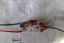
Printed circuit board of the second layout option.

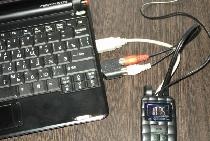
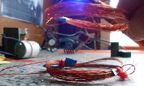
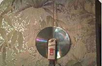
Another article was not completed until the end, and people are already messing up. They pass exams very well. Dmitry sent pictures of his device (see below).
Amplifier (option number 1)
Transmitter Amplifier # 2. It’s never easier. The difference is that you have to wind the coil for resistance indicated in the diagram. (instead of speaker)
Amplifier circuit
Wireless headphone for exams
(Option 2 - continued)
How to make an amplifier (transmitter):
one). We buy an ordinary Chinese radio with automatic tuning, without a speaker. Any model is suitable as the circuit is practically no different.
2). We disassemble the radio.
but). We find the chip. Carefully remove the 2, 4, 5 legs. (If you look at the chip from above, and assume that the first leg is next to the mark).
b) We find a headphone jack. We find the socket foot, which sends a signal to the middle pin of the plug (if the plug is stereo). We find the path that goes from this leg and cut it. In general, the socket will be adapted for a mono plug. An antenna worn around the neck will be stuck there.
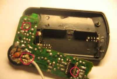
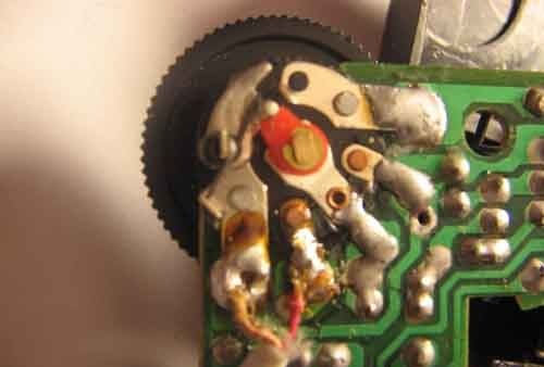
at). We find a variable resistor, which is a volume control and a switch. His two extreme contacts go to hundsfree instead of an earphone (see photo_1).
3). We cut a place for the hundsfree wire in the radio case. We cover everything as it was in the case. The amplifier is ready to use! (see photo_1)
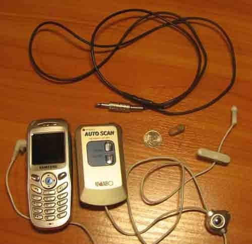
Photo 1
We connect the phone to hundsfree (hundsfree should go with the phone!). In the amplifier (former receiver), instead of the headphones, we stick the antenna.
Hundsfree:
Hundsfree does not need special revision! Instead of an earphone, we connect an amplifier. You can open the hundsfree button and pull out the microphone from there. Make it on a separate wire (see photo_1). Most importantly: hundsfree must be matched to the specific phone model. Otherwise, there may be problems with sound.
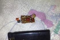
Earpiece
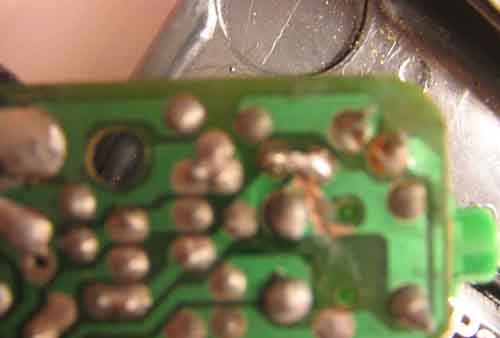
The headphone coil is wound directly on the telephone capsule (TEM) along it! After winding, it is convenient to fix the turns on the capsule using super-glue. The headphone parts are mounted on the board, which simplifies the assembly process and allows you to solder chip parts of size 0805 and smaller. The battery location is located behind the earphone. The board is located above the battery. Headphones turn out from one end a little thicker, which holds him well in the ear and prevents him from getting into the brain! : 0)
The battery contacts are cut out of a copper screen (from some kind of coil) and soldered to the board. The capsule with the coil wound on it can also be glued with super-glue to one of the battery contacts (through the gasket). The entire system is driven into a shrink tube with a diameter of 9-10 mm. and with the help of a building hair dryer or an ordinary candle, it is gently brought into a ready state (at the same time, the battery must be inserted into the earphone and the tube on the wide side of the earphone to be clamped with tweezers, after cooling, a beautiful seam will form in the clamped place, which can be trimmed with nippers). See photo.
I wanted to add specifically for crazy pens! In order not to buy or break the receiver even if it is Chinese, let's turn to its circuit. see below
From it we see that most of it is not used, but the whole amplifier is used, the AF assembled on two transistors! We can replace them with domestic ones, for example, KT3102. It will not be worse, or maybe better. This amplifier is capable of distorting to give power, which will be enough for high-quality operation of the headphone. But there are pitfalls, this scheme will not give high-quality sound and it will be at the level of industrial designs! But we twist radio lovers and do not stop there.
Amplifier ZCH better can be assembled on one cheap microcircuit and four discrete elements. I hope you do not need to explain what we will include instead of the headphones? Yes, the transmitter coil is sluggishly hanging from the neck.
So we come to the final part of the article. And we put a bullet on this.
Wireless headphone for exams
(Option 2 - ending)
Manufacturing option.
We assemble the radio headphone, the assembly of which will be discussed, according to the scheme (Fig. 1), which was already previously presented. To do this, we will need all the radio components (SMD) shown in the diagram, the TEM-1958 electromagnetic telephone, a heat shrink tube (preferably flesh-colored) and an enamelled wire of 0.04-0.05 mm (it can be obtained by breaking the Chinese alarm clock).
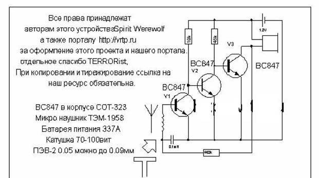
Fig. one
First of all, we make a printed circuit diagram on a computer, because it is already ready, we just download, print and manufacture the board directly.
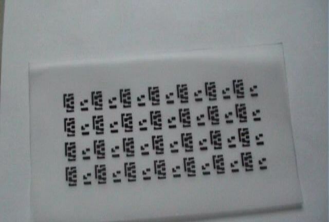
Fig. 2
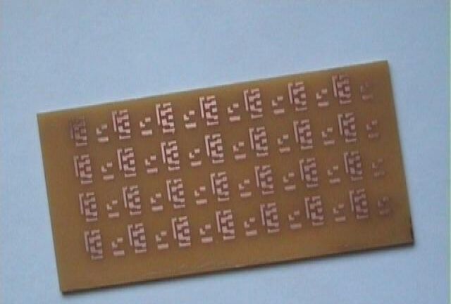
Fig. 3
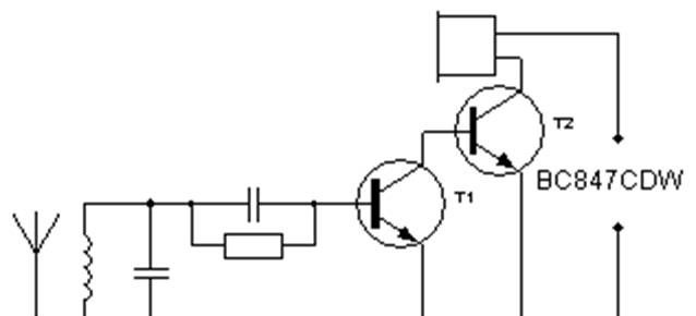
The printed circuit diagram, as can be seen in the figure, consists of two separate parts. On the main board are: V1-V3 transistors and 10K and 43K resistors. On the second board are located: a 0.1mF capacitor and a 560K resistor.
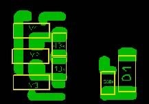
Fig. four
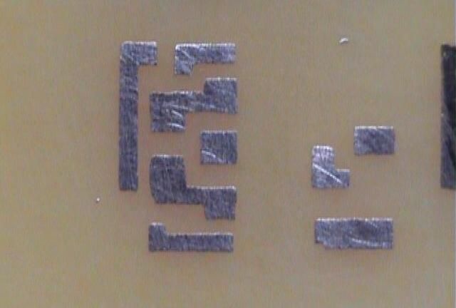
Fig. 5
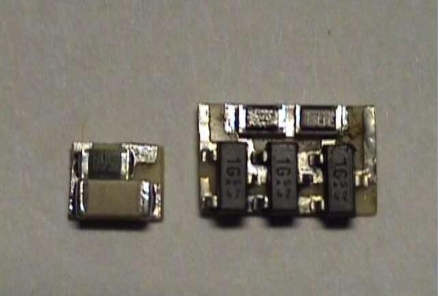
Fig. 6
Since the radio earphone should be as compact as possible, therefore, the board must also be manufactured with utmost care. In order for the boards cut in this way to be not only small in area (Fig. 6), but also in thickness, we begin to very carefully and painstakingly grind the surface of the board from the back side, and for one nails as well. For starters, it’s best to use a large emery cloth well, and only then when the back surface is polished to a minimum (the main thing is not to overdo it!) We take as much fine sandpaper as possible and carefully modify the surface remembering that both boards will stick to the TEM case -1958.
Further, as expected, soldering of elements follows. It is best to solder on some kind of metal surface that will absorb excess heat, because when soldering so many thin boards, tracks can go away! (Well, however, it all depends on your ability to solder). We glue ready-made boards with reliable superglue so that the boards are joined together (Fig. 9), solder the junction (just the place where the capacitor connects to the transistor emitters). Sticking out the edges with a scalpel!
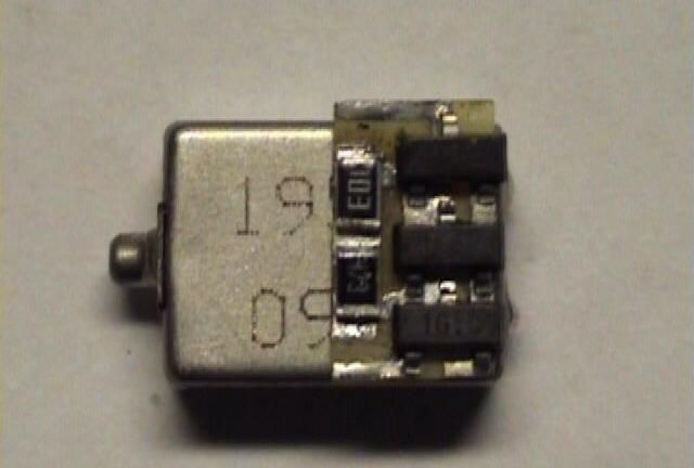
Fig. 7
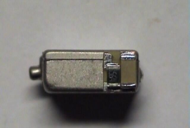
Fig. 8
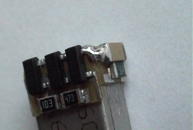
Fig. 9
Now we take a coil (Fig. 10) with the previously mentioned enamelled conductor and wind 70-100 turns on the remaining free space on the TEM-1958 and solder its ends to the boards according to the scheme. For reliability, you can drop a little glue on the coil. Using a conductor with a large diameter can lead to self-excitation of the earphone (high-frequency squeak).
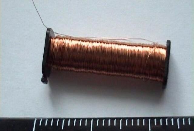
Fig. 10
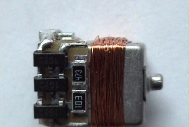
Fig. eleven
If the workpiece looks like this, then you are in the right direction!
For the manufacture of a battery fassung we use tin (can be removed from the old battery) and the material for the manufacture of circuit boards. From the tin, we cut out the main part of the fassung body (which is also the “+” terminal), see Fig. 12. From the material for the manufacture of circuit boards, cut a circle with a diameter of 6 mm and again take the sandpaper and grind the surface and, without that, bleeding fingers to a minimum, this is our cleme “-”. As a result, the fassung looks like this. fig. 13.

Fig. 12
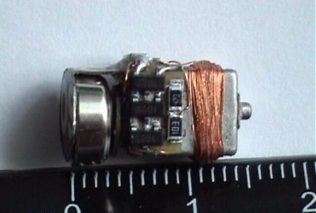
Fig. 13
Now came a very crucial moment "Installing the fassung." If you do not concentrate now, then consider the matter a failure! First of all, we solder the “+” terminal to one of the TEM-1958 contacts (it’s better to the right if you look at the marking side and considering that the contacts are on top) you need to do this very carefully and quickly, because these contacts disappear very quickly and then everything Hemorrhoids! Well, if everything worked out, then you can continue further, so that this cleme does not fall away and does not spoil your mood, then you need to properly glue it or fill it with two-component superglue (its durability is 250 kg / cm?, It is possible and weaker), at the same time) glue the “-” clamp (But before that, do not forget to connect the second TEM contact with the circuit, otherwise it will be too late!) The “+” clamp should not be in contact with the housing!
After the glue dries well, we add, according to the scheme, the missing connections, for this we use an enameled conductor. In places where it will pass, we spill with a moderate amount of Chinese second glue so that it does not cross (insulation).At the end, we place the resulting structure in a heat-shrink tube (the battery should be in the fusee!), Heat it with a building hair dryer or a lighter, hold the heated tube on the battery side with tweezers, and carefully remove the sticking limbs with a scalpel. A properly assembled headphone will produce a slight hiss!
Fig. fourteen
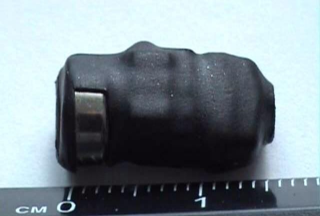
Fig. fifteen
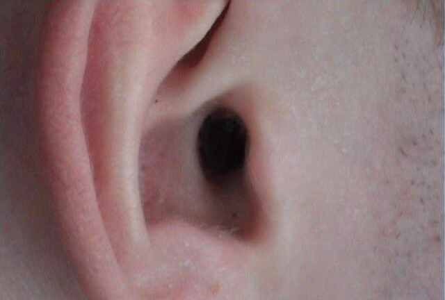
Fig. 16
So it looks in the ear!
The manufacture of the transmitter antenna is outlined in previous articles!
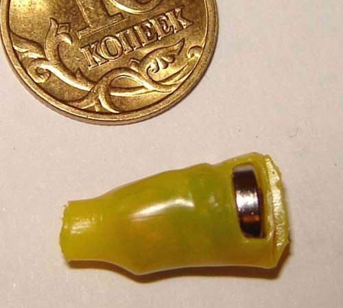
Wireless micro-earpiece on a chip
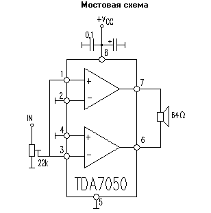
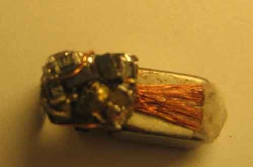
I assembled for today's exam all this installation on the TDA7050 chip, both an amplifier for the loop and the earphone itself.
For the loop I used a chip in a conventional case. The wiring diagram is similar to stereo (lower), only connected together the 2nd and 3rd legs, and 7 and 8 go separately to the capacitors. But after them, not 2 speakers, but connected together and on a loop (purely by ear, the sound is more powerful than using the mono version, i.e. the upper 1st circuit), the second end of the loop is naturally negative.
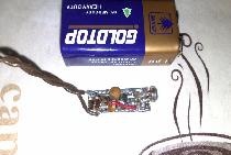
The loop wound 32 ohms. I took the battery from the Samsung X100 as a battery.
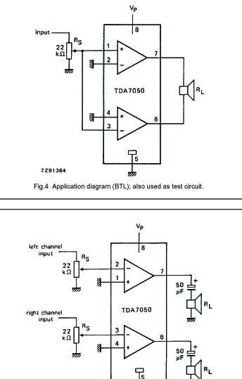
If possible, it is better to assemble an amplifier for the loop using m / s TDA7052, the headphone catches much better!
In the earphone itself, I used a chip in the SMD housing. The speaker took from Nokia (the one that seems to be 60 Ohms). Assembled according to the first scheme, but only without any resistors and capacitors, i.e. I connected a coil to the input (without capacitors and resistors !!!), which I wound on a microcircuit.
And so that there was more resistance, I just wound more turns (for 12-13 minutes I shook 0.01 mm in the manual wire until the wire itself broke, in this place and attached it to the minus).
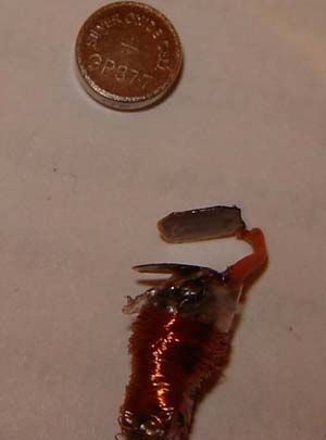
I used two LR41 batteries (paunchy ones, but they fit). And so I learned a lot, for me the most optimal option, because I don’t sell small parts in my city at all, I didn’t immediately find the microcircuit. The size of the "ear" is basically normal, but let's say it might not fit in with my classmate.
Here are the pictures, though these are draft versions (a body made of paper to hold batteries at least somehow), because I have not yet found the heat-shrinkable tube of the desired diameter.
Well, here’s what’s under the paper, of course, you need to do more tightly

Perhaps the most important part: a coil wound directly on a chip mounted on a speaker. Everything was soldered with a 45 cotton soldering iron, because There is nothing particularly complicated and there are no small details either: only the microcircuit and speaker from Nokia, and of course the coil is natural.
Of course, if everything is done more carefully and the batteries are smaller, then you can still win 1-1.5 mm in diameter and in the battery area. Only the diameter of the speaker cannot be changed in any way, unless the speaker is smaller. My version is 9 mm long with batteries. The diameter in the area of the speaker itself is 8 mm, where the batteries are up to 8 mm (depending on which batteries to put).
I also used 361A batteries, they are the same in diameter as the LR41 but thinner. 361A lasts for at least about 1.5 hours, I can’t say for sure, I checked it with old batteries. The current between them and the ear is approximately 5-6 mA (this is measured by a cheap old Chinese tester). But according to the manual for the chip, it is written that at 3V the current consumption is 3.2 mA.
As for noise, the speech and music in the headphone can be heard and heard, but the fewer turns, the less you hear, but also less hiss. The more turns, the better you can hear both speech and hissing, though there is a certain limit, beyond which speech begins to disappear and hissing and sensitivity to all kinds of devices increase even more. You can, leaning your ear against the wall, to determine without any problems where the wiring passes.
Good luck everyone!!!!
P.S. All information presented is used for self-education !!!! The site administration, as well as the author of the article, does not bear any responsibility for the misuse of information and any negative consequences.
Tip: If someone suffered from acute inflammation of the inner ear, which manifests itself in the fact that at some point the pus accumulated in the ear canal breaks the eardrum and goes outside, then it is better not to use this ear !!!!!!!!!!
The eardrum heals, but it is not fully contracted, leaving some hole. Also, after that, hearing loss by 10-15% is possible (changing timbre color, high frequencies are heard worse).