DIY do it yourself
Master classes, instructions, useful tips, recipes.
» » »Simple radiation detector

I decided to use a small ionization chamber with a current amplifier built on a composite transistor as a sensor.
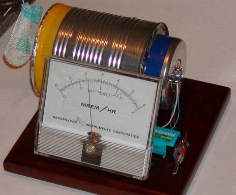

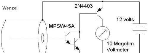
But when I connected the base of the composite transistor directly to the sensor wire, the collector current was practically absent. I expected to see some leakage current due to the floating base and tens of thousands gain. I don’t know if all of the composite npn transistors are as good as these MPSW45As, but the leakage current was surprisingly low and the gain looked very high, maybe 30,000, with a base current of several tens of picoamperes. (I checked the gain with a test resistor with a resistance of 100 MΩ connected to a power source with an adjustable output voltage).

Suddenly, I saw an opportunity to use these conventional components to make a truly sensitive sensor. I added another transistor as shown below


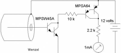
Who needs bias resistors ?! I used a can with a diameter of about 10 cm with a hole in the bottom for the antenna wire and aluminum foil covering the open part. I quickly realized that a resistor connected to a 2N4403 base (10 kOhm) is a good idea to prevent damage during a short circuit. The efficiency of this circuit was excellent; it easily detected the Coleman lamp thorium grid! So why not add another composite transistor? It seemed ridiculous, but here is what I built:


I used a 9 V supply voltage, but would recommend using a slightly higher voltage to get enough potential in the ionization chamber. Resistors have been added to protect against accidental short circuits, which can quickly damage a transistor or ammeter. During normal operation, they have little effect on the functioning of the circuit.

This circuit really works well, and after 5-10 minutes needed to stabilize, it could detect a glow grid at a distance of about ten centimeters. But the circuit turned out to be sensitive to temperature changes and the ammeter readings increased with a slight increase in temperature in the room. Therefore, I decided to add temperature compensation by constructing an identical circuit, but without a sensor wire connected to the base of the transistor, and turning on the measuring device between the output points of both circuits:


It looks a bit confusing, but actually quite easy to do. The circuit was assembled in the same can as used in one of the JFET projects described above, and all parts of the circuit were mounted on an 8-pin circuit board. An attentive reader will notice that I actually used resistors with a resistance of 2.4 kOhm and 5.6 kOhm, but these differences in the ratings do not play a big role. I also used a blocking capacitor connected in parallel with a battery with a rating of, for example, 10 uF. The sensor wire is directly connected to the base of the transistor and passes through a hole drilled in the bottom of the can. The circuit is quite sensitive to electric fields, so it’s a good idea to have a shell like this.
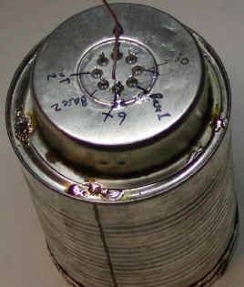
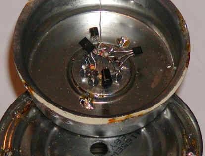
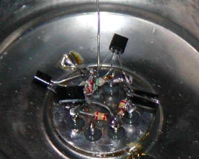
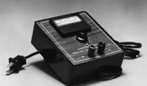
Let the circuit “warm up” a few minutes after applying the supply voltage, after which the ammeter should decrease to very small values. If the ammeter readings are negative, switch the sensor wire to the base of another transistor and change the polarity of the ammeter connection. If a noticeable voltage drops on resistors with a resistance of 2.2 kOhm, it can be up to one volt, try to clean everything with a solvent and completely dry. When the ammeter readings become low and stable, bring a radioactive source, such as a glow gauge, to the window covered with foil, and the readings should increase rapidly. A digital voltmeter with a scale of up to 1 V or an ammeter with a scale of 100 μA can be used as a measuring device. The meter shown below already has a scale calibrated in units of radioactivity, and a reading of about 2.2 is due to the effect of the glow grid.
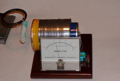
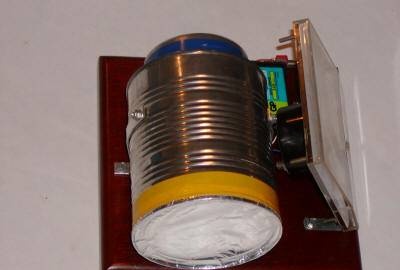

This is a simple sensor, given its sensitivity! An active experimenter can try other transistors, most likely composite ones, for example, MPSA18, or even an operational voltage-controlled current amplifier, for example, CA3080 with an open feedback loop.

come back
Comments (26)
  1. Admin4126
    #1 Admin4126 Guests March 27, 2011 17:46
    0
    What do you think, can you use ordinary low-power transistors according to the composite circuit?
  2. NOTFRONT
    #2 NOTFRONT Guests March 27, 2011 18:23
    0
    can try. e.g. ct 3102
  3. Admin4126
    #3 Admin4126 Guests March 27, 2011 21:16
    0
    That is, transistors with a high current transfer coefficient are practically suitable? If so, is it possible to use a low-noise operational amplifier instead of these composite transistors, for example KR551UD1A, where the central wire inside the can is connected to one input and the second input is left in the "air". If I'm not mistaken, the idea should be the same.

    [center][/ center]

  4. NOTFRONT
    #4 NOTFRONT Guests March 27, 2011 21:24
    0
    I don’t know ... And why do transistors not pin you? it’s easier on them!
  5. Admin4126
    #5 Admin4126 Guests March 27, 2011 23:57
    0
    I agree, I will try to assemble for a start on transistors. Another question, I can’t imagine where in Moldova to find the heating grid of a Coleman gas lamp? Can I use something else for tuning, I don’t know, for example, radiation from a DRL lamp? What do you advise?
  6. NOTFRONT
    #6 NOTFRONT Guests March 28, 2011 07:27
    0
    From DRL will not roll. I myself would have collected such a little thing if it were something to granulate or at least check the robots.

    To check, you can go to Japan! biggrin

  7. NOTFRONT
    #7 NOTFRONT Guests March 28, 2011 18:59
    2
    [center][/ center]
  8. Tyger
    #8 Tyger Guests May 12, 2011 16:13
    0
    and what apermeter is needed for this device? What is it called simply A μA mA cool
  9. NOTFRONT
    #9 NOTFRONT Guests May 12, 2011 16:52
    1
    At a response current of 1 mA, can apply 100 μA
  10. Rybak27
    #10 Rybak27 Guests May 28, 2011 12:28
    0
    Did, it seems to work
    [center][/ center]
    Indications are constantly different. If you bring your hand, then the readings increase 2 times.
    Domestic transistors, CT315G, CT361E, CT503B.
  11. NOTFRONT
    #11 NOTFRONT Guests May 28, 2011 12:42
    0
    Of course they will increase, your back (the circuit itself) is not shielded!
  12. Rybak27
    #12 Rybak27 Guests May 28, 2011 13:02
    0
    Shielded, the arrow moved to the beginning. Set measurements from 10 mA to 500 μA. Now the arrow is constantly moving.
  13. NOTFRONT
    #13 NOTFRONT Guests May 28, 2011 13:10
    0
    and how are you going to check it for radiation?
  14. Rybak27
    #14 Rybak27 Guests May 28, 2011 13:18
    0
    I do not know smile
  15. Rybak27
    #15 Rybak27 Guests May 28, 2011 13:24
    0
    Do you have some ideas?
  16. NOTFRONT
    #16 NOTFRONT Guests May 28, 2011 13:53
    0
    Yeah, I already suggested going to Japan ... biggrin
  17. Rybak27
    #17 Rybak27 Guests May 28, 2011 13:56
    0
    but seriously?
  18. Rybak27
    #18 Rybak27 Guests May 28, 2011 15:00
    0
    All this is attached to the bank, everything is shielded. Now the arrow is near the middle and does not move, only sometimes it can twitch.
  19. Veent
    #19 Veent Guests May 29, 2011 14:40
    0
    I heard that near the Tesla coils not weak radiation is detected, well, or just brute force to the electromagnetic field reacts
  20. Dmitry Vladimirovich
    #20 Dmitry Vladimirovich Guests January 7, 2013 20:54
    0
    The use of OS is more competent, if only because of greater temperature stability, but it is advisable to use the conclusions of the internal balance of the OS. In addition, it is preferable to use the IN-13 or at least other large neon necks, for example, from stroboscopes of old vinyl turntables, as a sensor. You can try and pulsed as IFC-120. In any case, glass-tight will be much less dependent, for example, on humidity. But the plan is generally not bad.
  21. Dmitry Vladimirovich
    #21 Dmitry Vladimirovich Guests January 7, 2013 20:56
    0
    [b] NOTFRONT [/ b],
    Not always what is simple - reliable. wink
  22. Byko Maxim
    #22 Byko Maxim Guests June 24, 2015 16:38
    0
    Come to the freight tracks to check, they are not badly consumed with radiation for some reason, because they often transport radioactive waste through them.
  23. Alexey
    #23 Alexey Guests August 23, 2015 13:33
    0
    on the 1 diagram, the wrong labeling of transistors is all 3 pieces of PNP structure
  24. Person
    #24 Person Guests November 2, 2015 00:10
    0
    I'm glad to test. Background can be near the boiler room, which use coal fuel! The slag that is formed after the combustion of coal contains a certain amount of rad. substances. Usually, a so-called dump from slag accumulates near the boiler room. (in common ash) The longer the slag was dumped there, the higher it was. background! (I hope it’s clear why)> = |; 0)
  25. Oleg
    #25 Oleg Guests June 8, 2016 03:39 a.m.
    0
    [b] Man [/ b],
    And where now are they left boiler rooms on coal?
  26. LMC
    #26 LMC Guests April 14, 2018 5:36 p.m.
    0
    Simpler and better on the LMC660 op amp is 2phA (femto amperes) and a gain of 126dB (2,000,000 times). Only this op-amp and giga ohm resistor are needed. Well, μA head or multimeter.

Read also

Error codes for washing machines