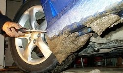
This year, when I needed a charger, it turned out that it had become unusable - the contacts had rusted and began to “pierce” into the case. Due to the fact that the ardor of amateur radio has diminished over the years, I decided to buy a pulse generator - an automatic machine, so that there would be less hassle - according to the principle, turn it on (when necessary), turn it off (when the charge stops), and forget it until the next need. The choice of pulse chargers is quite large, but it seems that Chinese friends have successfully modified Danish or Italian radio circuits, as a result of which modern devices differ from each other only in build quality.Many manuals reproduce complete nonsense: “...the device automatically cleans the terminals of sulfates...” - apparently this nonsense is reprinted by people who do not know the difference between the terminals and the anode of the battery, where sulfation occurs (Pb2SO4 + H2SO4 + O, equals 2PbSO4+H2O). This process, which intensifies during discharge, causes destruction of the electrode, and the pulsed charge seems to remove or reduce sulfation.
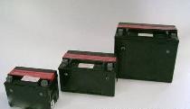
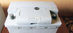
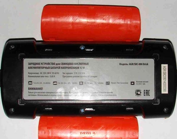
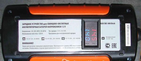
So, there are no fundamental differences between impulse chargers - automatic machines (everyone writes about seven- or nine-stage charging, in my opinion this is pure advertising ploy, especially since there remains the possibility for further flight of thought, such as twenty-stage, thirty-stage , etc.), so based on the battery power, you need to choose something cheaper. In my case, this is a device with a ridiculous name for the Aggressor charger (AGR/SBC-080 Brick) at a price as of 02.2016. 2750 rubles with a desulfation function and a charging current of up to 8A, designed to charge batteries up to 160 Ah.

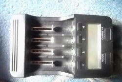
The device looks good in appearance - good thick (but terribly smelly) plastic, due to the well-fitted rubber gasket there are no complaints about the seams, the device is intuitive, but there is one “BUT” - there is no indication of voltage and current. In some cases, a “winter” charge with a current of 8A automatically jumps to a 2A charge (motorcycle battery), while LEDs show the charge, and an additionally connected ammeter shows its absence.Chargers with indication of current and voltage are an order of magnitude more expensive - around $200, meanwhile, a simple modification of any, I emphasize, any charger using an ampere-voltmeter, for example, for 250 - 300 rubles, will turn your device into a more attractive and convenient one in use equipment.
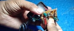
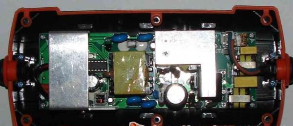
The ampere-voltmeter can be placed either in the charger itself (if there is room for it), or outside it - in a special box, connecting it to the wires going to the battery for charging. To select a location, we will inspect the charger by pressing out the side plastic covers and unscrewing 6 screws. Having removed the cover, you can see that an ampere-voltmeter cannot be placed on the front panel - otherwise you will have to change the board. There are several places to output the ampere-voltmeter to the rear panel; I chose one closer to the charging cables.
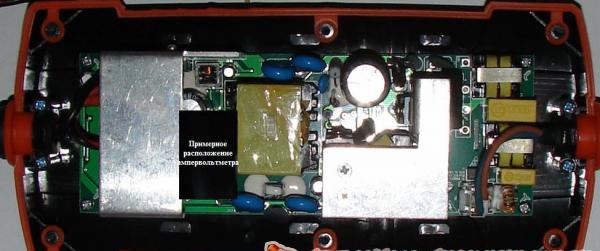
Approximate location of the ampere-voltmeter. Having trimmed the ampere-voltmeter body a little with pliers, I positioned the device inside the body as conveniently as possible (slightly to the left of the center line), after which I carefully turned the charger over, saving the place where the ampere-voltmeter will be installed in the charger body and outlined the hole. Next, it’s a matter of home appliances - in 15 minutes I drilled about 40 holes on the inside of the outlined rectangle with a thin drill using a drill or screwdriver, with the same drill I combined them and freed up a window for the ampere-voltmeter. Having straightened the edges with a file, I installed the ampere-voltmeter in the window and secured it with hot glue. The ampere-voltmeter is tightly and quite firmly placed in the window, does not protrude beyond the limits of the limiter, while almost all the information on the rear has been preserved.
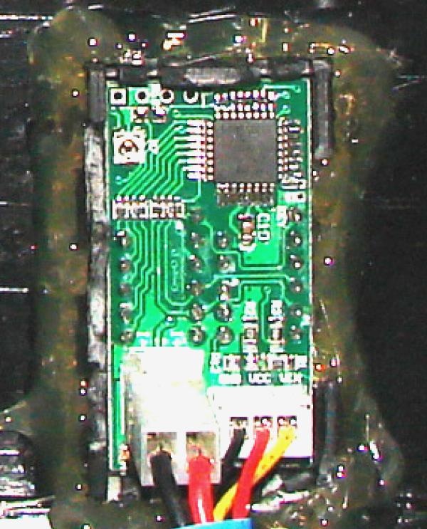
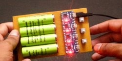
Next, having cut the (-) negative wire of the charger (black), we solder the black wire of the ammeter to the top (the ammeter has two thick wires - red and black), and to the bottom of the wire going to the battery - the red wire of the ammeter and the black wire of the voltmeter. We solder the red and yellow wires of the voltmeter to the bare (+) positive wire of the charger (there are three voltmeter wires - yellow, red and black, they are thinner). We cover the soldering points with heat shrink or electrical tape, and you can start charging.
By connecting the (+) and (-) terminals to the battery, you can see its voltage on the display of the ampere-voltmeter, and the charging current will appear after turning on the device and selecting the mode.
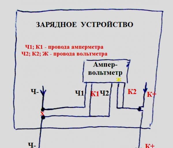
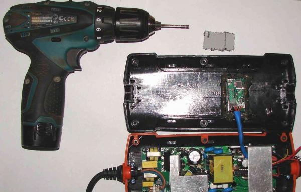
There is one inconvenience - the mode switch button is on the front side, and the ampere-voltmeter is on the back, but this only slightly requires rework. As you can see, the alteration did not affect the circuit diagram, but only affected the cables going to the battery being charged, and therefore an external option for placing the ampere-voltmeter in a small case is possible for both this charger and any other.
Best regards, Vadim Zakharov.